


SETTING FOR RS-485 USE
The RS-485 interface can be used to operate the VCR
using a SANYO brand system controller.
NOTES:
œ This can only be used when the RS-485 interface
board (VZU-40485) is installed.
œ Refer to the instruction manual for the VZU-40485
and/or the system controller.
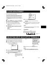
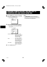
Setting the Address and Data Transfer
Speed
œ Make this setting without a cassette tape inserted.
1
Press the PLAY button for 3 seconds or more.
ø “Ad” and the address number appear on the
digital display.
2 Press the l (or j) button to set the VCR address
(from 000 to 127).
ø The address set appears on the digital display.
3
Press the ENTER button.
4
Press the l (or j) button to set the data transfer
speed (19200, 2400, 4800, 9600).
ø The data transfer speed set appears on the
digital display.
5
When finished, press the PLAY button.
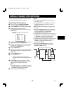
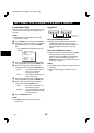
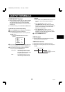
6
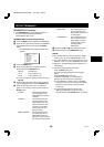
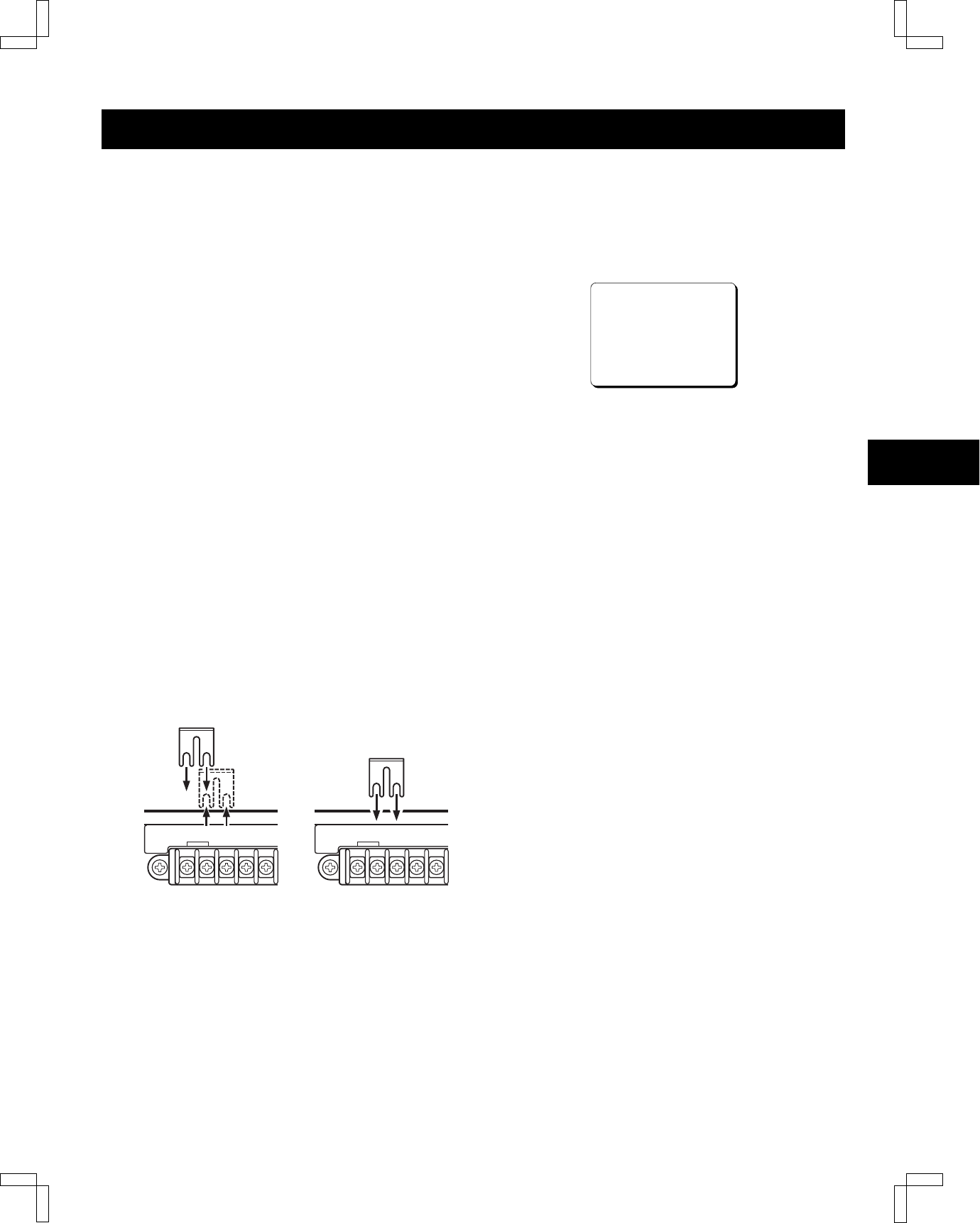
Move the shorting bar of the RS-485 interface board
to change the TERMINATE setting.
ON (Terminated) OFF (Not terminated)
NOTE:
œ When the MENU RESET button is pressed, the
setting appearing on the digital display is reset to the
default setting.
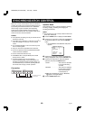
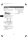
Settings when using RS-485
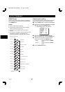
1 Press the MENU button to display the MAIN MENU.
2 Press the l (or j) button to select the “9.OTHERS”
line, then press the ENTER button.
ø The (OTHERS) menu appears.
<OTHERS>
*ALARM@LOG
*POWER@FAILURE/DEW
*TERMINAL@SET@@@@SET1
*RS-485@SET
@@STATUS@INFO.@@@Y
@@ALARM@INFO.@@@@Y
3
Press the l (or j) button until the “STATUS INFO.”
setting is highlighted, then press the ENTER button.
4
Press the l (or j) button to set the “STATUS
INFO.” setting, then press the ENTER button.
Y. . . . . . . . . . The VCR status information is
output at the RS-485 connector.
N. . . . . . . . . . The status information is not
output at the RS-485 connector.
5
Press the l (or j) button until the “ALARM INFO.”
setting is highlighted, then press the ENTER button.
6
Press the l (or j) button to set the “ALARM INFO.”
setting, then press the ENTER button.
Y. . . . . . . . . . The VCR alarm information (alarm
recording start and stop) and
video loss information are output
at the RS-485 connector.
N. . . . . . . . . . The VCR alarm information (alarm
recording start and stop) and
video loss information are not
output at the RS-485 connector.
7
Press the MENU EXIT button.
NOTE:
œ When a warning state (non-recording, mechanical
problem or clog detection) occurs, the warning state is
output from the RS-485 connector. However,
non-recording warning states are not output if “NON
REC” is set to “N” in the (WARNING OUT/CONTROL
SET) menu. In addition, the clog detection warning
state is not output if “CLOG DETECT.” is set to “N” in
the (GENERAL SET) menu.
SHORT FOR
TERMINATION.
COM COM
SHORT FOR
TERMINATION.
NB4QR/NA (SRT-4040 GB) Tue. Sept., 10/2002
42
English