LC-52LE920UN/LC-60LE920UN
7. Microprocessor software writing
7.1. Main microprocessor/monitor microprocessor software writing (Main PWB: QPWBXF452WJZZ)
Adjustment item Adjustment conditions
Software Version Up
File version check
USB memory check
* When IC is failure
Main microprocessor/moni-
tor microprocessor soft-
ware writing
<Main PWB>
Adjustment procedure
1. Insert a USB memory for the main/monitor microprocessor into the service con-
Rector.
2. Supply AC power and write the main software to IC8401 and the monitor micro-
processor software to IC2002.
3. Check that writing is normally completed and turn off the power.
CAUTION: When the USB memory is not inserted or reading error occurs, nothing
is written. (The former models have read the main software from the
writing jig. However, this model reads the main/monitor software from
the USB memory.)
Please exchange to another PWB unit when IC8401 (NAND Flash) is failure.
(Because the software can't be written with USB memory, when the new IC is
exchanged from broken IC)
7.2. Model/inch discrimination writing (Main PWB: QPWBXF452WJZZ)
When writing the sub microprocessor software, the model data is configured with the software from the USB memory mounted to the checker.
Reference and setting change are enabled through the process menu and RS-232C communication.
8. Signal adjustment
8.1. LCD section adjustment [LCD module adjustment]
Adjustment item
Opposite bias adjustment
(LCD module adjustment
item)
Adjustment conditions
Adjustment in the center
position of the panel
Adjustment procedure
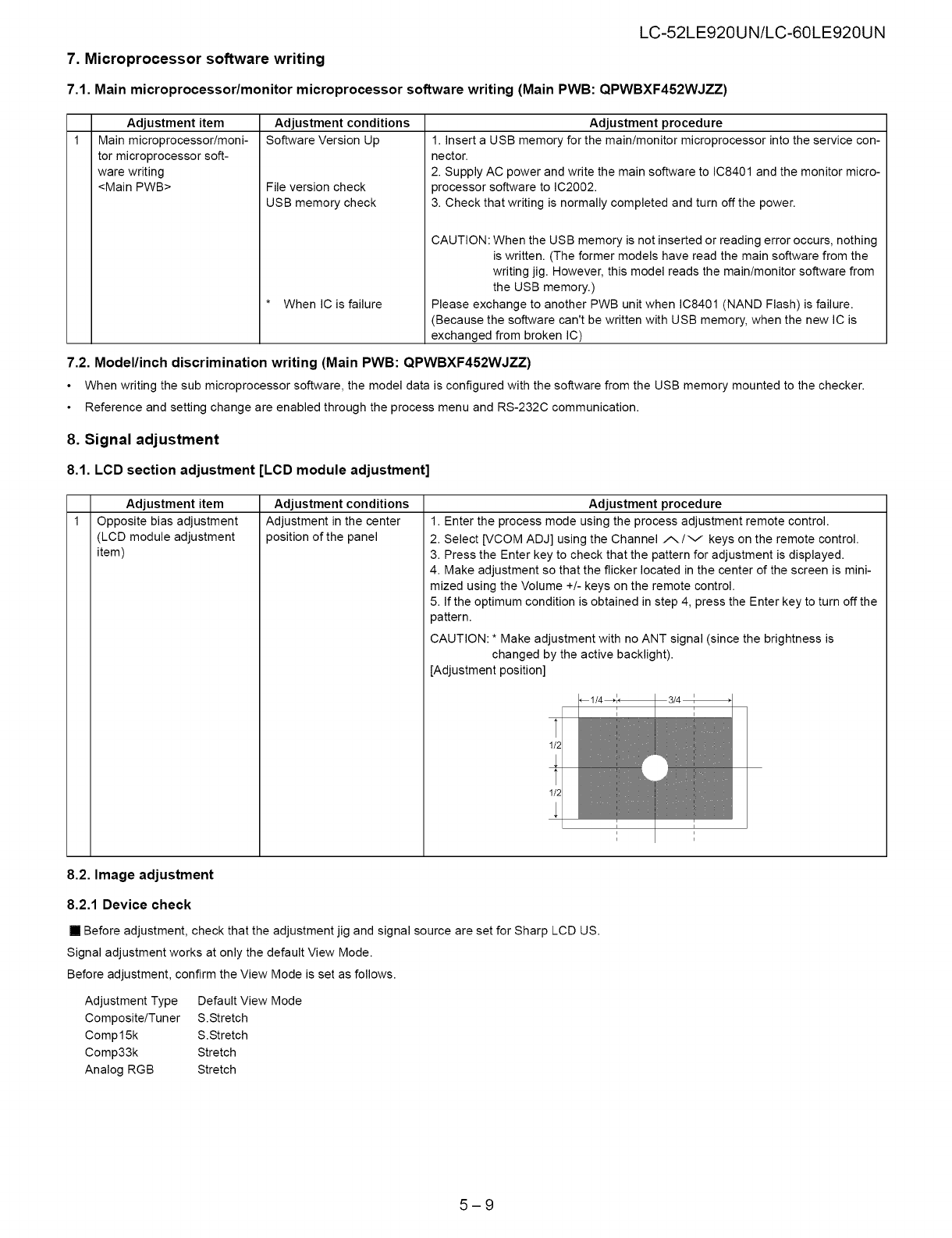
1. Enter the process mode using the process adjustment remote control.
2. Select [VCOM ADJ] using the Channel ./_/v keys on the remote control.
3. Press the Enter key to check that the pattern for adjustment is displayed.
4. Make adjustment so that the flicker located in the center of the screen is mini-
mized using the Volume +/- keys on the remote control.
5. If the optimum condition is obtained in step 4, press the Enter key to turn off the
pattern.
CAUTION: * Make adjustment with no ANT signal (since the brightness is
changed by the active backlight).
[Adjustment position]
//I
i
i
i
3/4
8.2. Image adjustment
8.2.1 Device check
[] Before adjustment, check that the adjustment jig and signal source are set for Sharp LCD US.
Signal adjustment works at only the default View Mode.
Before adjustment, confirm the View Mode is set as follows.
Adjustment Type Default View Mode
Composite/Tuner S.Stretch
Compl 5k S.Stretch
Comp33k Stretch
Analog RGB Stretch
5-9


