


— 18 —
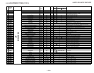
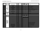
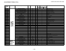
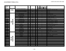
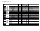
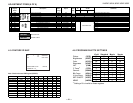
KV-32FV27 / 36FS13 / 36FS17 / 36FV27 / 38FS17
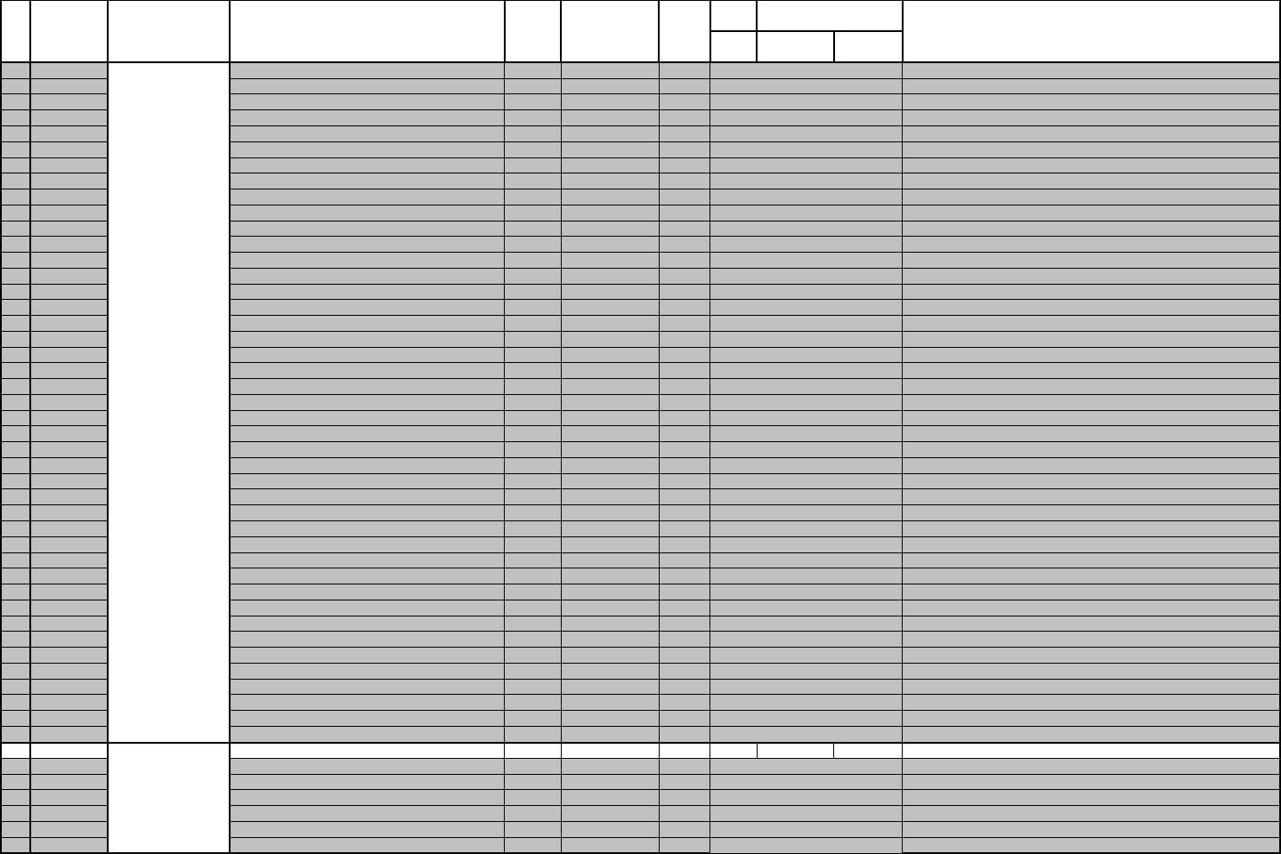
ADJUSTMENT ITEMS (3 OF 6)
Description Data Adj/Fix Initial 32" 36"/38" Comments
Range Data FV FS FV
Register
Name
24
ST0S
Select ST0 Pin Output Signal
0-3
FIX 1 1
External Y-ADC clamp pulse
25
WSC
Noise Detection Coring
0-3
FIX 1 1
1LSB coring for noise detection circuit
26
VTRH
H-sync Non-Standard Detection Hysteresis
0-3
FIX 1 1
Low hysteresis (2 clock pulses)
27
VTRR
H-sync Non-Standard Detection Sensitivity
0-3
FIX 1 1
Medium sensativity (+/- 8 clock pulses)
28
LDSR
Frame Sync Non-Std Detection Sensativity
0-3
FIX 2 2
Low sensativity (1.5 clock pulses)
29
PWRE
Internal ADC Input Range
0,1
FIX 0 0
Same input range on Y-ADC and C-ADC
30
VAPG
Vertical Aperture Compensation Gain
0-7
FIX 4 4
0: Correction OFF, 7: Max Correction
31
VAPI
Vertical Aperture Comp Convergence
0-31
FIX 12 12
0: Correction OFF, 31: Max Correction
32
TEST
Test Bit
0,1
FIX 0 0
Normal Mode
33
YPFT
Y Peaking Filter Center Frequency
0-3
FIX 3 3
4.22 MHz
34
YPFG
Y Peaking Filter Gain
0-15
FIX 7 6
0: -1 gain, 15: 0.875 gain
35
V1PS
Horizontal Dot Supression Level
0-3
FIX 2 2
Medium suppression
36
VEGS
Vertical Dot Supression Level
0-3
FIX 2 2
Medium supression
37
CC3N
Line Comb C Separation Filter
0,1
FIX 0 0
Narrow bandwidth
38
C0HS
C Signal Delay Time at NR
0,1
FIX 0 0
1H Delay
39
CLPH
Y-ADC Clamp Test Bit
0,1
FIX 0 0
Normal Mode
40
SEL2
DC Detection High Freq Sensativity
0,1
FIX 0 0
Low sensativity, Close to still pictures
41
SEL1
DY detection Low Freq Sensativity
0,1
FIX 0 0
Low sensativity, Close to still pictures
42
YHCO
Y High Freq Coring
0-3
FIX 1 0
Small Amount of coring (+/- 1LSB)
43
YHCG
Y High Freq Coring Gain
0,1
FIX 0 0
Gain = 1
44
OVST
Non Standard Detection Test Bit
0,1
FIX 0 0
Normal Mode
45
CSHD
H/V counter Test Bit
0,1
FIX 0 0
Normal Mode
46
KCTT
H/V counter Test Bit
0-3
FIX 0 0
Normal Mode
47
SHT
Non Standard Detection Test Bits
0,1
FIX 0 0
Normal Mode
48
VCT
H/V counter Test Bit
0,1
FIX 0 0
Normal Mode
49
OTT
H/V counter Test Bit
0,1
FIX 0 0
Normal Mode
50
CL2D
Clock Generator Test Bit
0,1
FIX 1 1
Normal Mode
51
CGGT
Clock Generator Test Bit
0,1
FIX 0 0
Normal Mode
52
CLEB
Clock Generator Test Bit
0,1
FIX 0 0
Normal Mode
53
CGT
Clock Generator Test Bit
0,1
FIX 0 0
Normal Mode
54
HPLL
Horizontal PLL Filter
0,1
FIX 1 1
Quick convergence
55
BPLL
Burst PLL Filter
0,1
FIX 1 1
Quick convergence
56
FSCF
Burst Extraction Gain
0,1
FIX 0 0
High gain
57
PLLF
PLL Loop Gain
0,1
FIX 1 1
High gain, quick convergence
58
KILR
Killer Detection Reference
0-15
FIX 3 3
0: Detection off, 15: High detection sensativity
59
HSSL
Horizontal Sync Slice Level
0-15
FIX 12 12
0: 4LSB, 15: 19LSB
60
VSSL
Vertical Sync Slice Level
0-15
FIX 8 8
0: HSSL + 0LSB, 15: HSSL + 15LSB
61
BGPS
Burst Gate Start Position
0-15
FIX 5 5
0: Hsync center + 2ms, 15: Hsync center +5.75ms
62
BGPW
Internal Burst Gate Pulse Width
0-15
FIX 10 10
0: 0.5ms, 15: 4.25ms
63
ADCL
ADC Clock Delay
0-3
FIX 3 3
0: 0ns, 3: 20.5ns (typical)
64
ADPD
ADC Power Down
0,1
FIX 1 1
Stop ADC when not in use
65
NSDW
Non Standard Detection Test Bit
0,1
FIX 0 0
Normal Mode
66
CNRF
CNR Section Test Bit
0,1
FIX 0 0
Normal Mode
0
SHPR
Controls both DL APACON and SRT
0-127
Fix by Model 52 52 59 52
0: Minimum, 127: Maximum
1
BLAD
Black Area Detect
0-3
FIX 0 0
0: 10IRE, 1: 20IRE, 2: 30IRE, 3: 40IRE
2
SRTS
SRT Start Amplitude
0-3
FIX 3 3
0: 7IRE, 1: 10IRE, 2: 14IRE, 3: 28IRE
3
YNR
Controls YNR ON/OFF
0,1
FIX 1 1
YNR ON
4
GIRE
Gamma Correction Start Point
0-3
FIX 3 3
0: 70IRE, 1: 80IRE, 2: 90IRE, 3: OFF
5
DAC1
1 bit DAC Output
0,1
FIX 0 0
Open
6
DAC2
1 bit DAC Output
0,1
FIX 0 0
Open
PIC IMP
TA1226
N
3D COMB
uPD64082