


— 22 —
KV-32FV27 / 36FS13 / 36FS17 / 36FV27 / 38FS17
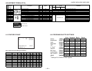
TO PROGRAM PROGRAM PALETTE RESET
LEVELS
1. Switch to Program Palette to edit.
2. Enter Service Mode.
3. Set desired values for current Program Palette settings.
4. Write into memory by pressing
MUTING
then
ENTER
.
5. Repeat steps 1-4 for each palette.
Example
To Set RESET Level of Standard Mode to 60%
1. Switch to STANDARD Palette.
2. Enter Service Mode.
3. Change value of VPIC to 38 (38/63 = 60%)
4. Write into memory by pressing
MUTING
then
ENTER
.
5. Enter Video Menu and press
RESET
.
6. Reset level of picture for STANDARD PALETTE ONLY is now 38
steps.
4-7. A BOARD ADJUSTMENTS
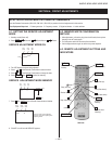
SUB CONTRAST ADJUSTMENT (RDRV,
RDR4)
1. Input a 75% color-bar signal.
2. Set to: VIDEO mode = Standard, COLOR = Minimum,
PICTURE = 100%, GON = 0 (OFF), BON = 0 (OFF)
3. Set to Service Adjustment Mode and connect an oscilloscope to
pin
1
of CN351 on the A Board.
4. Set RDRV with
1
and
4
.
5. Adjust with
3
and
6
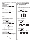
for: 1.85 ± 0.05 Vp-p (KV-32FV27 ONLY),
1.95 ± 0.05 Vp-p (ALL EXCEPT KV-32FV27).
6. Write into memory by pressing
MUTING
then
ENTER
.
7. Repeat steps 1-6 for RDR4 using Video 4 input.
1.95 ± 0.05 Vp-p (ALL EXCEPT KV-32FV27)
White
Black
1.85 ± 0.05 Vp-p (KV-32FV27 ONLY)
SUB BRIGHT ADJUSTMENT (SBRT)
1. Set to Service Adjustment Mode.
2. Input a gray scale pattern signal.
3. Set the PICTURE to minimum, and BRIGHT to normal.
4. Select SBRT with
1
and
4
.
5. Adjust SUB BRIGHT level with
3
and
5
so that the stripe second
from the right is faintly visible.
6. Write into the memory by pressing
MUTING
then
ENTER
.
white
black
second from the right
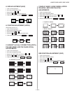
SUB HUE, SUB COLOR ADJUSTMENT
(T2HU, T2CO, V2HU, V2CO, 4SHU, 4COL)
Note: T2HU and T2CO are for Tuner inputs.
V2HU and V2CO are for all other Video inputs.
4SHU and 4COL are for Video 4 input.
1. Input a 75% color-bar signal.
2. Set to Service Adjustment Mode and set: VIDEO mode = Standard,
PICTURE = 100%, COLOR = 50%, HUE = 50%.
3. Connect an oscilloscope to Pin
3
of CN351 on the A Board.
4. Select T2HU and T2CO with
1
and
4
.
5. Adjust with
3
and
6
for a fl at ± 50mV.
6. Write into memory by
MUTING
then
ENTER
.
7. Repeat steps 1-6 for V2HU & V2C0 and 4SHU & 4COL.
V1
V2 V3
V4
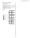
V. SIZE ADJUSTMENT (VSIZ)
1. Input a cross-hatch signal.
2. Set to Service Adjustment Mode.
3. Select VSIZ with
1
and
4
.
4. Adjust with
3
and
6
for the best vertical size.
5. Write into the memory by pressing
MUTING
then
ENTER
.
V. POSITION ADJUSTMENT (VPOS)
1. Input a cross-hatch signal.
2. Set to Service Adjustment Mode.
3. Select VPOS with
1
and
4
.
4. Adjust with
3
and
6
for the best vertical center.
5. Write into the memory by pressing
MUTING
then
ENTER
.