


Chapter 1 Overview
Chapter 1 Overview 27
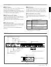
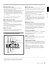
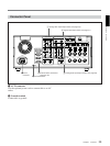
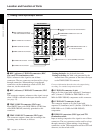
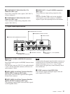
3 REC (record) INHIBIT switch
When this switch is set to ON, the REC INHIBIT
indicator in the display section lights, and recording on
tape is no longer possible. (See the description of
extended menu item 107.)
4 KEY INHIBIT switch
When this switch is set to ON, the KEY INHIBIT
indicator in the display section lights, and the buttons
in the upper control panel and lower control panel
specified by the setting of extended menu item 118 are
disabled.
5 PROCESS CONTROL switch
This selects the method of control of the internal
digital video processor.
REMOTE: Select this position to use an optional
remote control unit for remote control of the
internal digital video processor.
MENU: Select this position to use the setup menu to
change the settings for the internal digital video
processor.
LOCAL: Select this position to use the subsidiary
control panel to change the settings for the internal
digital video processor.
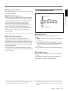
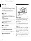
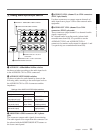
6 INT/EXT–PRESET/REGEN (internal/external−
preset/regenerated) switch
This switch is used to make selections relating to the
time code and the internal time code generator.
(In this Operating Instructions, this switch may also be
called simply as the INT/EXT switch or PRESET/
REGEN switch depending on the contents of the
description in which the switch is referred to.)
Selection of internal/external time code
Selection relating to the internal time code generator
7 FREE RUN/REC RUN switch
This switch selects the time code run mode of the
internal time code generator.
FREE RUN: Regardless of the operating mode of
this unit, the time code value advances
continuously while the power is on.
REC RUN: The time code value advances only
during recording. When this mode is selected, set
the INT/EXT−PRESET/REGEN switch to INT−
PRESET.
8 DF/NDF (drop-frame/non-drop-frame) switch
(for the DSR-2000A only)
This switch selects the mode of advancing the time
code generator and time counter.
DF: Drop-frame mode
NDF: Non-drop-frame mode
Note
When the PRESET/REGEN switch is set to REGEN,
since the time code generator is synchronized to the
playback time code, this switch has no effect.
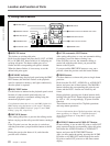
9 VITC switch
To record the time code produced by the internal time
code generator as a VITC, set this switch to ON.
When this switch is set to OFF, internally generated
time code is not recorded as VITC, but VITC present
in the input video signal is recorded unchanged.
!º TC (time code) SELECT switch
This switch selects the time code, TC or VITC, shown
in the time counter display.
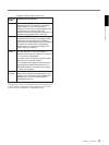
Setting
Operation of the internal time code generator
PRESET The initial value of the time code produced by
the internal time code generator can be preset
by a control panel operation or by remote control
from a device connected to the REMOTE-IN or
REMOTE-OUT connector.
REGEN The internal time code reader is synchronized to
the playback time code read by the internal time
code reader.
Setting
Time code used
INT
The time code produced by the internal time
code generator
By setting the switch to INT–REGEN or INT–
PRESET, you can select “PRESET” or “REGEN”
for the internal time code generator
(see the
next table)
.
EXT The external time code selected as follows.
• When the TC SELECT switch is set to TC
The external time code input to the TIME
CODE IN connector
• When the TC SELECT switch is set to VITC
The VITC time code included in the input
video signal
In this case, for the internal time code generator,
“REGEN” is always selected
(see the next
table)
.