


Chapter 2 Location and Function of Parts
2-8 Chapter 2 Location and Function of Parts
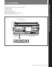
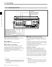
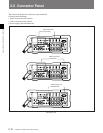
2-1 Front Panel
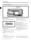
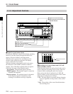
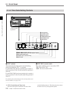
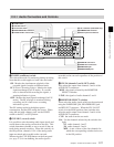
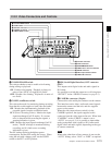
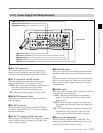
2-1-4 Time Code Setting Controls
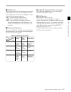
1 VITC switches
These determine the lines in the vertical blanking
interval in which the VITC
1)
is recorded.
For the DVW-250, the factory default is for switch A
to be in position 6 (line 16) and switch B in position 8
(line 18).
For the DVW-250P, the factory default is for switch A
to be in position C (line 19) and switch B in position E
(line 21).
For details of the relation between the switch positions and
the line numbers, see page 4-10.
Pull the projecting
lug forward.
A VITC
REC DISPLAY
B OFF VITC
R-RUN
F-RUN ADVANCE SHIFT REAL TIME
EXT-LOCK/U-BIT
SET
DIAG
SET
SET
VITC U-BITOFF NDF
DFONLTC U-BIT
REC
OFF
ON
ON LTC
Time code setting controls
1 VITC switches
2 VITC REC switch
3 DISPLAY switch
4 F-RUN/R-RUN switch
5 ADVANCE button
6 SHIFT button
7 REAL TIME record/set switch
8 REAL TIME insertion time code selection switch
9 EXT-LOCK/U-BIT switch
0 DF/NDF switch (DVW-250 only)
!¡ DIAG switch
..........................................................................................................................................................................................................
1) VITC (Vertical Interval Time Code)
This time code signal is inserted in two lines of the
vertical blanking interval. This allows the time code to
be read even at very slow playback speeds.
2 VITC REC (record) switch
This selects whether or not to record the VITC.
ON: Record the VITC.
OFF: Do not record the VITC.