


Chapter 4 Recording
Chapter 4 Recording 4-3
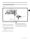
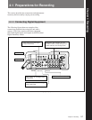
4-1-3 Making Video Input Settings
Selecting the input video signal
This unit accepts three different types of video input
signals, selected by the video input selector switch as
follows:
• To select a composite video signal input to the
VIDEO IN connector, select the left position (VIDEO
IN).
• To select the signal input to the CAMERA (26-pin)
connector, select the center position (CAMERA).
There is a setup menu operation to select between
using analog (Y/R-Y/B-Y) or digital signals. It is
also possible to set the unit to determine the type
automatically from the type of camera connected.
For details of the setup menu operation, see Section 6-3
“Setup Menu Settings,” item “CAMERA” in the <VIDEO
1> menu (page 6-3).
• To select serial digital video and audio signals input
to the SDI IN connector, select the right position
(SDI IN).
The SDI format includes audio signals, but there is a
setup menu operation to determine whether to use
these as the audio input, or to use separate analog
inputs.
For details of the setup menu operation, see Section 6-3
“Setup Menu Settings,” items “INPUT 1/2” and “INPUT
3/4” in the <AUDIO> menu (page 6-4).
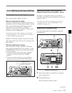
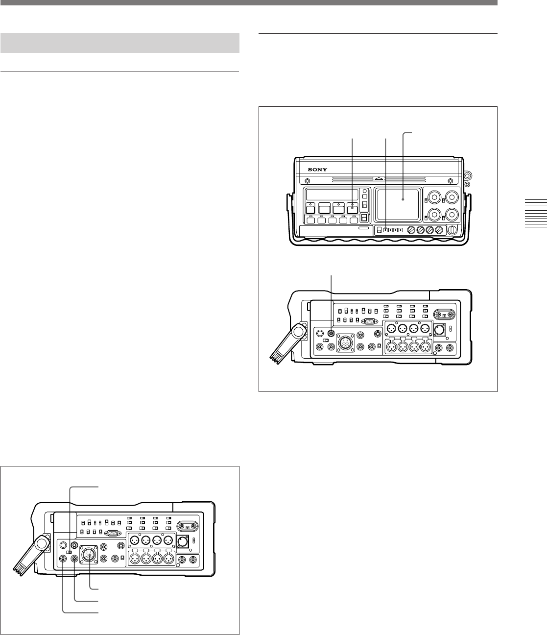
Selecting the input video signal
Video input selector switch
SDI IN connector
CAMERA connector
VIDEO IN connector
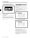
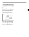
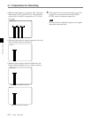
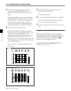
Displaying and adjusting the video input
levels
It is possible to check the video input levels, using the
level meters.
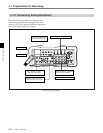
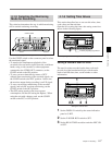
Displaying and adjusting the video input levels
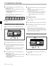
1 Press the REC button.
The unit switches to the E-E mode.
2 Press the DISPLAY button in the adjustment
controls.
Pressing the DISPLAY button cycles the display
through the audio level meters, video level meters,
and setup menus.
If the display is showing the video level meters or
setup menus, and five minutes elapse without an
operation, the display automatically reverts to the
audio level meters.
12
3
Signal level and
menu display
(Continued)