5-16 Chapter 5 Recording/Playback
5-4 Playback
Chapter 5 Recording/Playback
$$$
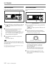
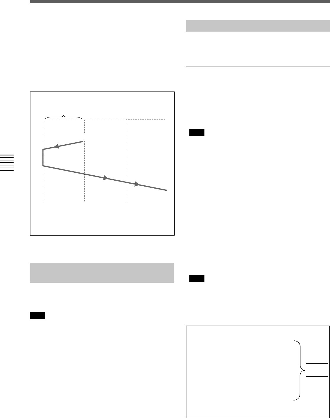
Press the PREVIEW button.
Preroll time ×
initial speed
IN point
Speed variation
end point
Tape runs at
initial speed
Playback mode
using the
memorized speed
Playback at
normal speed
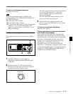
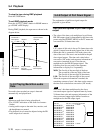
To stop the tape during DMC playback
Press the STOP button.
To exit DMC playback mode
Press the ALT/[F7] (DMC) button in HOME menu to
go off DMC on the display.
During DMC playback, the tape runs as shown in the
diagram below.
DMC playback
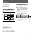
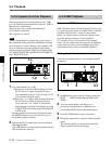
5-4-5 Playing Back Non-audio
Data
Non-audio data recorded on a tape is detected
automatically and played back.
Note
When non-audio data is being played back:
• The “OVER” indication on the audio level meters
flashes.
• Analog audio output to the main line, monitor, and
the headphones are muted.
• The playback level cannot be adjusted using the PB
audio output level controls.
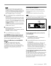
5-4-6 Output of Pull Down Signal
The explanation of pull down signal output for
playback is given below.
Time code multiplexed to pull down signal
output
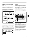
• The value of the time code multiplexed to pull down
HD SDI output signal is determined by the time code
preset using the PDPSET MENU in the TC menu and
converted into 30-frame time code.
Note
LTC output of this unit is always 24-frame time code
which is output from the main output line of this unit.
• When this unit is operated in 24F mode, time code
data of the user’s bits area is not included in the pull
down signal output. The time code value before
conversion (24F mode) and sequence information of
conversion contained in user’s bits data are
multiplexed to the HD SDI output signal. The
following four bits are used for the sequence
information to display 0 to 9 repeatedly.
MSB: The first bit of the tens digit of the hour
The second bit of the tens digit of the hour
The first bit of the tens digit of the minute
LSB: The first bit of the tens digit of the second
When the sequence information is masked, the
remaining contents of user’s bits data are the same as
the time code value before conversion (24F mode).
Note
Since user’s bits data multiplexed to the down-
converted output signal are updated frame by frame,
24-frame time code and sequence information of the
down-converted output signal differs from those
multiplexed to the HD output signal.
00:00:00:00
00:00:00:00
00:00:00:01
00:00:00:01
00:00:00:02
00:00:00:02
00:00:00:03
00:00:00:03
00:00:00:04
00:00:00:04
00:00:00:05
00:00:00:05
00:00:00:00
00:00:80:00
00:80:00:01
00:80:80:01
40:00:00:01
40:00:80:02
40:80:00:02
40:80:80:03
80:00:00:03
80:00:80:03
00:00:00:04
00:00:80:04
*
*
*
*
*
*
Time code area
30F TC
User’s bits area (HD)
24F TC + sequence information
A frame
A frame
Cycle of
conversion


