


– 42 –
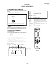
KV-ES29M90
RM-916
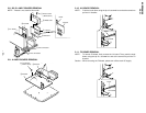
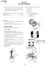
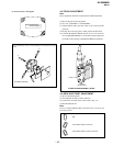
5 Y separation axis correction magnet adjustment.
1. Receive the cross-hatch signal and adjust [PICTURE] to [MIN]
and [BRIGHTNESS] to [STANDARD] .
2. Adjust the Y separation axis correction magnet on the neck
assembly so that the horizontal lines at the top and bottom of
the screen are straight.
Note
1. The Red and Blue magnets should be equally far from the
horizontal center line.
2. Do not separate the Red and Blue magnets too far. (Less than
8 mm)
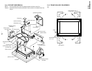
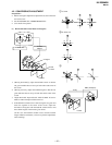
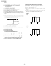
(2) Dynamic Convergence Adjustment
Preparation:
• Before starting this adjustment, adjust the horizontal static
convergence and the vertical static convergence
• Set the PICTURE and BRIGHTNESS to normal.
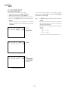
1. Adjust TLH. (TLH correction piece)
1 Receive the dot/hatch pattern signal and adjust picture quality
by the menu.
2 Correct horizontal mis-convergence of red and blue of both sides
on the X axis.
When red is outside insert BMC magnet to right side (THL+)
views from DY neck. And when blue is outside, insert it to left
side (THL–) and take both sides.
2. Adjust XCV core.
To able to become balance of XCV on the X axis well.
3. Adjust V-TILT.
Correct the vertical mis-convergence of red and blue of verti-
cally sides on the Y axis.
4. Adjust YCH.
Adjust horizontal mis-convergence of red and blue of verti-
cally sides on the Y axis. Mentioned above steps 2 to 4 are
adjusting respectively perform minuteness tracking.
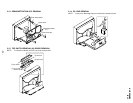
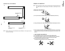
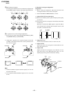
4 BMC (Hexapole) Magnet.
If the red, green and blue dots are not balanced or aligned, then
use the BMC magnet to adjust in the manner described below.
RG B R G B R GB
RB
RG
G
GB
RB
Blue
Red
VM board
Blue
Red
VM board
Neck assy Neck assy
R
(B)
B
(R)
B
(R)
TLH +
TLH -
R
(B)
XCV
BMC magnet
C board
RV9001
VM board
TLV1
YCH
TLV2