


24 (GB)
Watching the Picture
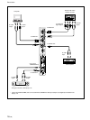
INPUT2 YUV: Selects the audio and video signal
input from the INPUT2 connectors when
the input signal is a component signal.
VIDEO COMPOSITE: Selects the audio and
video signal input from the COMPOSITE
IN connector and AUDIO IN jack among
the VIDEO connectors.
VIDEO Y/C: Selects the audio and video signal
input from the Y/C IN connector and
AUDIO IN jack among the VIDEO
connectors.
(For the PFM-42B1E/42B2E, VIDEO
COMPOSITE and VIDEO Y/C only appear when
the BKM-B10 video input adaptor or BKM-B13
video input & control S adaptor (not supplied) is
installed.)
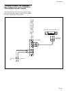
INPUT3 RGB: Selects the input signal (RGB
signal) from the device connected to the
INPUT 3 connector. (Only when the
BKM-B12 component adaptor is
installed.)
INPUT3 YUV: Selects the input signal
(Component signal) from the device
connected to the INPUT3 connector.
(Only when the BKM-B12 component
adaptor is installed.)
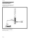
INPUT3 PC: Selects the signal from the BKM-
B30NW network adaptor installed in the
VIDEO connector unit.
(Only when the BKM-B30NW network
adaptor is installed.)
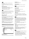
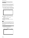
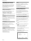
The selected input signal appears on the display
panel.
PAL
VIDEO COMPOSITE
You can also switch the input signal using the
Remote Commander.
Note
We recommend input source video equipment
equipped with a TBC (time base corrector). If the
display receives a signal without TBC, the picture
may disappear due to disturbance of the sync signal.
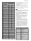
Color system or horizontal/vertical frequency
Signal type
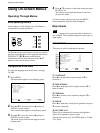
Watching the Picture
Before you start
• Turn on the display.
• Turn on the connected equipment and play a video
source.
• To display the input signal information on the screen
when turning on the power or switching the input
signal, set “DISPLAY” in the CONFIG (1/2) menu
to ON.
• To select the on-screen language used in the menu,
see page 36 (GB).
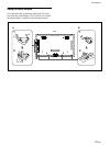
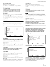
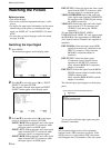
Switching the Input Signal
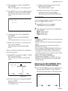
1 Press MENU.
The main menu appears on the display panel.
ENTER
MENU
MA I N MENU
I NPUT SELECT
PIC CONTROL
PIC SIZE
CONF I G
MEMORY
REMOTE
STATUS
SELECT SET END
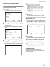
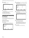
2 Press v / V to move the cursor (B) to “INPUT
SELECT” and press ENTER.
The currently selected input signal and INPUT
SELECT menu appear on the display panel.
ENTER
MENU
PAL
VIDEO COMPOSITE
INPUT SELECT
I NPUT1 RGB
I NPUT1 YUV
I NPUT2 RGB
I NPUT2 YUV
VIDEO COMPOSITE
VIDEO Y/C
SELECT SET END
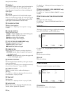
3 Press v / V to move the cursor (B) to the input
source to be displayed and press ENTER.
INPUT1 RGB: Selects the audio and video signal
input from the INPUT1 connectors when
the input signal is an RGB signal.
INPUT1 YUV: Selects the audio and video signal
input from the INPUT1 connectors when
the input signal is a component signal.
INPUT2 RGB: Selects the audio and video signal
input from the INPUT2 connectors when
the input signal is an RGB signal.