


Location and Function of Parts and Controls
25
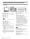
q RGB/COMPONENT button and lamp (for the
PVM-14L2/PVM-20L2 only)
Press this button to monitor the signal input through the
RGB/COMPONENT connectors.
r OPTION A button and lamp
This button works when an optional board has been
installed in the option slot on the rear panel. Press this
button to monitor the video signal input through input 1
of the optional board and the audio signal input through
the OPTION AUDIO INPUT 1 jack.
s OPTION B button and lamp
This button works when an optional board has been
installed in the option slot on the rear panel. Press this
button to monitor the video signal input through input 2
of the optional board and the audio signal input through
the OPTION AUDIO INPUT 2 jack.
(This button is disabled if BKM-129X or BKM-155DV
is used.)
t Tally lamp
Lights up when a video camera connected to this
monitor is selected. For the tally lamp to function
properly, certain cabling is required.
For details on this cabling, see page 33.
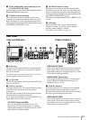
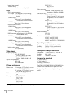
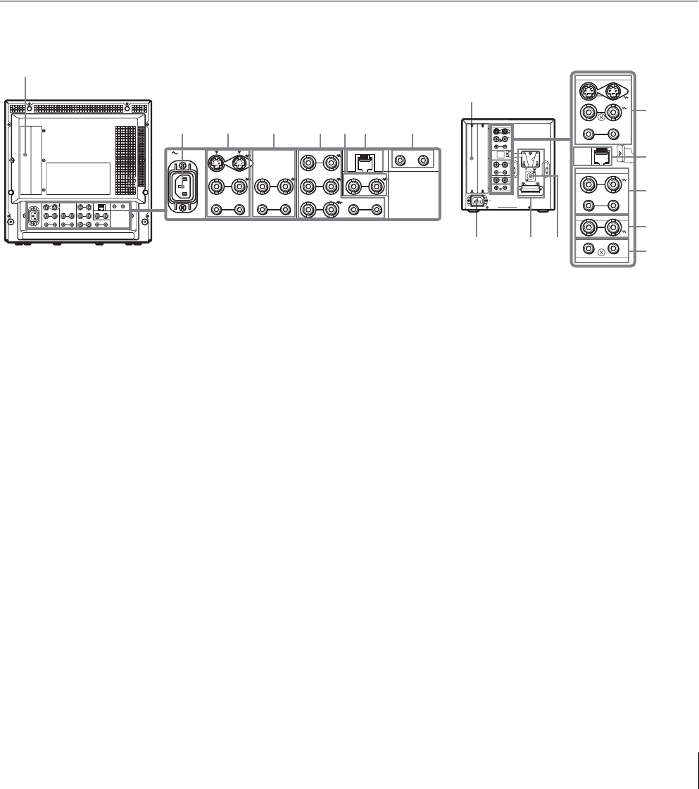
Rear Panel
a Option slot
You can install one optional board for expanding input
capability in this option slot. If you install two boards,
they do not function.
For details on how to install a board, refer to the user’s
manual supplied with the optional board.
b AC IN socket
Connect the supplied AC power cord to this socket and
then to a wall outlet.
c LINE A connectors
Line input connectors for Y/C separate, composite video
and audio signals and their loop-through output
connectors.
Press the LINE A button on the control panel to monitor
the input signal through these connectors.
If you input signals to both Y/C IN and VIDEO IN, the
signal input to the Y/C IN is selected.
Y/C IN/OUT (4-pin mini-DIN)
These are the input/output connectors for a Y/C
separate signal. Connect them to the Y/C separate
input/output connectors on equipment such as a VCR,
video camera, or another monitor.
VIDEO IN/OUT (BNC)
These are the input/output connectors for a composite
video signal. Connect them to the composite video
input/output connectors on equipment such as a VCR,
video camera, or another monitor.
AUDIO IN/OUT (phono jack)
These are the input/output jacks for an audio signal.
Connect them to the audio input/output jacks on
equipment such as a VCR.
d LINE B connectors
Line input connectors for composite video and audio
signals and their loop-through output connectors.
Press the LINE B button on the control panel to monitor
the signal input through these connectors.
VIDEO IN/OUT (BNC)
These are the input/output connectors for a composite
video signal. Connect them to the composite video
input/output connectors on equipment such as a VCR,
video camera, or another monitor.
AC IN LINE A LINE B
VIDEO
AUDIO
IN OUT
IN
OUT
VIDEO
AUDIO AUDIO
PARALLEL REMOTE
OPTION AUDIO INPUT
RGB/COMPONENT
IN OUT
IN
OUT
B/PB
G/Y
R/P
R
IN OUT
IN OUT IN
OUT
EXT
SYNC
IN OUT
1 2
2
1
345678
1
3
7
4
6
8
2
129X
LINE A
LINE B
EXT SYNC
OPTION AUDIO INPUT
AC IN
IN OUT
IN OUTVIDEO
IN
PARALLEL
REMOTE
OUT
DC
12V IN
–+
AUDIO
IN OUTVIDEO
IN OUT
IN OUT
12
AUDIO
LINE A
LINE B
EXT SYNC
OPTION AUDIO INPUT
IN OUT
IN OUTVIDEO
IN
PARALLEL
REMOTE
OUTAUDIO
IN OUTVIDEO
IN OUT
IN OUT
12
AUDIO
9q;
PVM-14L2/PVM-20L2
PVM-9L3/PVM-9L2