


7-3
VPL-HS1
7-3
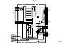
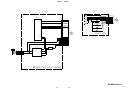
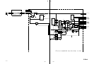
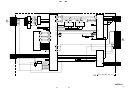
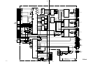
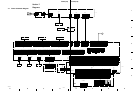
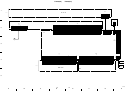
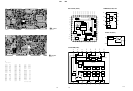
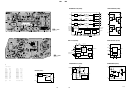
[Measuring conditions, voltage and waveform]
..
..
. A voltage value is the reference value between the measurement
point and the earth, when the RGB color bar signal is received
from the color bar generator (digital multi-meter used: 10 M ohms/
V DC).
..
..
. Unit of voltage is V (volt).
..
..
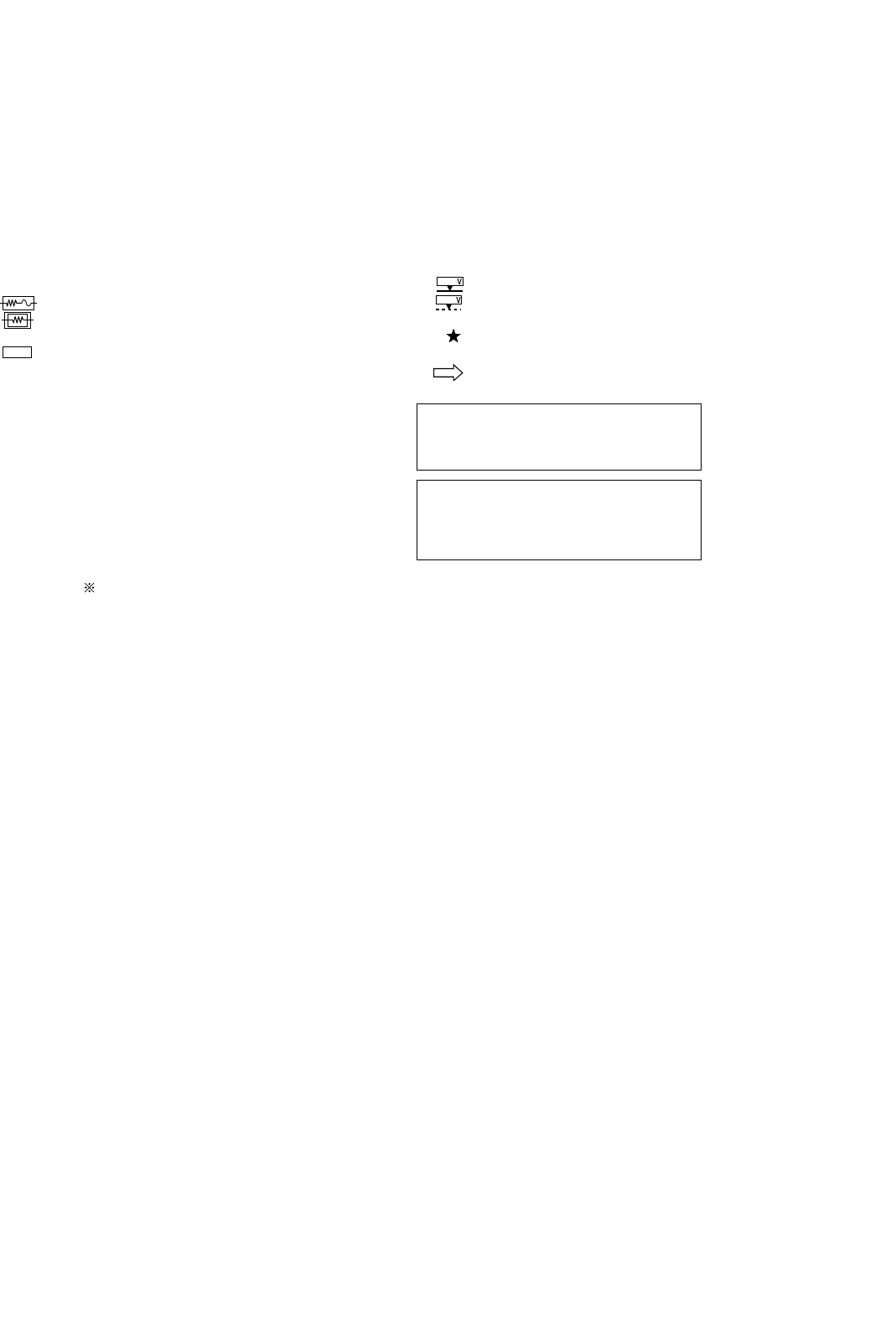
. : B+line
..
..
. : B– line
..
..
. Voltage variations may occur due to normal production tolerances.
..
..
. : Measurement disabled.
..
..
. Circled numbers indicate the reference waveform.
..
..
. : Signal path.
Les composants identifiés par la marque !
sont critiques pour la sécurité.
Ne les remplacer que par une pièce portant
le numéro spécifié.
Note:
..
..
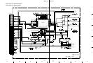
. Parts marked “ * ” differ according to the model/destination. Refer
to the mount table for each function.
..
..
. The parts marked “ # ” on schematic diagrams are not mounted.
..
..
. All capacitors are in µF unless otherwise noted. pF: µµF 50WV or
less are not indicated except for electrolytics.
..
..
. All electrolytics are in 50 V unless otherwise specified.
..
..
. : fusible resistor
..
..
. : nonflammable resistor
..
..
. ∆ : internal component
..
..
. : panel designation and adjustment for repair
..
..
. Caution when replacing chip parts
New parts must be attached after removal of the chip.
Be careful not to heat the minus side of a tantalum capacitor, be-
cause it is easily damaged by the heat.
Reference information
RESISTOR RN : METAL FILM
RC : SOLID
FPRD : NONFLAMMABLE CARBON
FUSE : NONFLAMMABLE FUSIBLE
RS : NONFLAMMABLE METAL OXIDE
RB : NONFLAMMABLE CEMENT
RW : NONFLAMMABLE WIREWOUND
: ADJUSTMENT RESISTOR
COIL LF-8L : MICRO INDUCTOR
CAPACITOR TA : TANTALUM
PS : STYROL
PP : POLYPROPYLENE
PT : MYLAR
MPS : METALIZED POLYESTER
MPP : METALIZED POLYPROPYLENE
ALB : BIPOLAR
ALT : HIGH TEMPERATURE
ALR : HIGH RIPPLE
The components identified marked ! are
critical for safety.
Replace only with the part number specified.
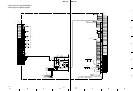
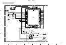
7-2. Schematic Diagrams and
Printed Wiring Boards