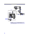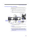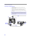
Connecting and Setting Up the DTV
11
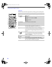
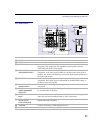
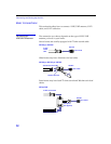
DTV Rear Panel
8
3
4
7
2
1
q;
9
5
6
qa
Connection Description
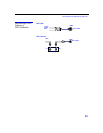
1 VHF/UHF
Connects to your VHF/UHF antenna.
2 CABLE
Connects to your cable source.
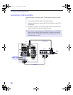
3 S VIDEO IN 1/3/4
Connects to the S VIDEO OUT jack of your VCR or other S VIDEO-
equipped video component. Provides better picture quality than the
VHF/UHF jacks or the Video IN jack.
4 VIDEO IN 1/3/4
VIDEO/L(MONO)-AUDIO-R
Connect to the audio and video OUT jacks on your VCR or other video
component. A 6th video input (VIDEO 2) is located on the front panel of
the DTV. The Audio and Video IN jacks provide better picture quality than
the VHF/UHF IN jack.
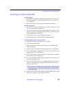
5 SELECT OUT Connect to the audio and video IN jacks on your VCR or other video
component. The output signal isdetermined by the
SELECT OUT
setting in
the Setup menu (see page 58).
6 AUDIO OUT (VAR/FIX)
L(MONO)-AUDIO-R
Connect to the left and right audio inputs of your audio or video
component.
7 HD/DVD IN
(1080i/720p/480p/480i)
VIDEO IN 5/6
Connect to your DVD player’s or digital set-top box’s componentvideo (Y,
P
B
,P
R
) and audio (L/R) jacks.
8 CONTROL S
IN/OUT
Allows the DTV to receive (IN) and send (OUT) remote control signals to
other Sony infrared-controlled audio or video components.
9 DIGITAL AUDIO
OPTICAL OUTPUT
(DOLBY DIGITAL/PCM)
Connect to the optical audio input of an audio component that is Dolby
Digital and PCM compatible.
0 i.LINK S200
Used for connecting i.LINK equipped devices.
qa Service Only
For Sony service use only.


