


Chapter 5: Advanced Motherboard Setup
5-13
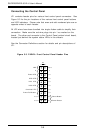
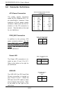
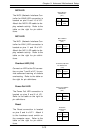
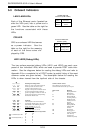
Overheat LED (OH)
Connect an LED to the OH connec-
tion on pins 7 and 8 of JF1 to pro-
vide advanced warning of chassis
overheating. Refer to the table on
the right for pin definitions.
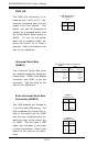
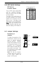
Reset
The Reset connection is located
on pins 3 and 4 of JF1. Attach it
to the hardware reset switch on
the computer case. Refer to the
table on the right for pin defini-
tions.
Pin
Number
3
4
Definition
Reset
Ground
Reset Pin
Definitions
(JF1)
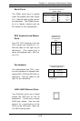
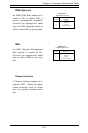
NIC2 LED
The NIC2 (Network Interface Con-
troller for LAN2) LED connection is
located on pins 9 and 10 of JF1.
Attach the NIC2 LED cable to dis-
play network activity. Refer to the
table on the right for pin defini-
tions.
NIC2 LED Pin
Definitions
(JF1)
Pin
Number
9
10
Definition
+5V
GND
Overheat (OH) LED
Pin Definitions
(JF1)
Pin
Number
7
8
Definition
+5V
GND
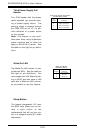
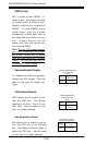
Power Fail LED
The Power Fail LED connection is
located on pins 5 and 6 of JF1.
Refer to the table on the right for
pin definitions.
Power Fail LED Pin
Definitions
(JF1)
Pin
Number
5
6
Definition
Control
GND
NIC1 LED
The NIC1 (Network Interface Con-
troller for LAN1) LED connection is
located on pins 11 and 12 of JF1.
Attach the NIC1 LED cable to dis-
play network activity. Refer to the
table on the right for pin defini-
tions.
NIC1 LED Pin
Definitions
(JF1)
Pin
Number
11
12
Definition
+5V
GND