


5-14
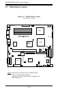
SUPERSERVER 6012L-6 User’s Manual
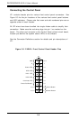
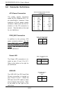
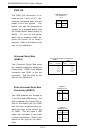
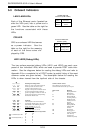
Extra Universal Serial Bus
Connection (USB2/3)
Two USB headers are located at
J1 for front side USB access. The
odd numbered pins (toward the in-
side of the board) are for USB2
and the even numbered pins (to-
ward the edge of the board) are
for USB3. You will need a USB
cable (not included) to use each
of these connections. Refer to the
tables on the right for pin defini-
tions.
Pin
Number
1
3
5
7
Definition
Power
-
+
Ground
USB2 Pin
Definitions (J1)
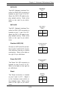
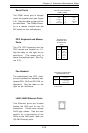
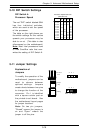
PWR_ON
The PWR_ON connection is lo-
cated on pins 1 and 2 of JF1. Mo-
mentarily contacting both pins will
power on/off the system. This
button can also be configured to
function as a suspend button (see
the Power Button Mode setting in
BIOS). To turn off the power
when set to suspend mode, de-
press the button for at least 4
seconds. Refer to the table on the
right for pin definitions.
Pin
Number
1
2
Definition
PW_ON
Ground
PWR_ON Connector
Pin Definitions
(JF1)
Pin
Number
2
4
6
8
Definition
Power
-
+
Ground
USB3 Pin
Definitions (J1)
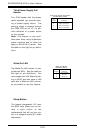
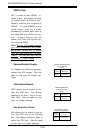
Universal Serial Bus
(USB0/1)
Two Universal Serial Bus ports
are located beside the keyboard/
mouse ports. USB0 is the bottom
connector and USB1 is the top
connector. See the table on the
right for pin definitions.
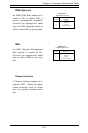
Universal Serial Bus Pin Definitions
Pin
Number Definition
1+5V
2P0-
3P0+
4 Ground
5 N/A
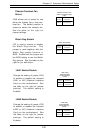
Pin
Number Definition
1+5V
2P0-
3P0+
4Ground
5Key
USB0
USB1