


4 of 6
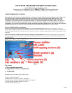
Place the fan on the bracket as shown in Figure 11. Screw in the four fan screws
(through the fan and into the bracket) until they are tight; do not overtighten.
Figure 11(above)
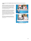
8. CONNECTING THE HARD DRIVES TO THE DRIVE BRACKET
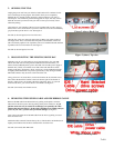
Using four of the hard drive screws included with your kit, screw your A/Master
drive to the bracket (the screws connect to the drives from the underside of the
bracket). In an "ADD" kit (in which you are retaining your factory drive), the
A/Master drive will be the factory drive. Be sure to orient the drive as shown in
Figure 12. The "A" drive should be connected near the bracket tab shown in Figure
12. In Figure 12, the IDE and power ports on the A drive are facing left. Do not
overtighten the screws.
Next, connect your new upgrade drive (or “B” drive) to the drive bracket using the
remaining four hard drive screws. Be sure to orient the drive on the bracket as
shown in Figure 12. When the B/Slave drive is connected and screwed in properly,
the back of the drive will hang off the end of the bracket. In Figure 12, the IDE and
power ports on the B drive are facing up. Do not overtighten the screws.
Figure 12
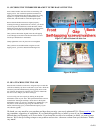
9. PREPARING THE CABLES
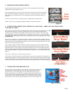
Once you have the drives and fan on the bracket, connect one end of the fan’s power pass-
through to the B/Slave drive (only one end will fit). Attach the other end to the power
splitter cable included with your kit. Attach the other end of the power splitter to the
A/Master drive. You should now have the fan cable and power cables running to each
drive on the bracket. See Figure 13.
Figure 13
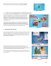
Take the IDE cable included with your kit and attach the BLUE connector to the
motherboard. NOTE: Be careful to insert the cable in the proper direction – each
connector on the cable has a notch that aligns to ensure it is not installed upside-down. See
Figure 14. Drape the remainder of the cable over the front of the unit.
Move the TiVo's internal red/yellow/black power connector over the back side of the
TiVo, as shown in Figure 14. You might have to flex or bend the power cable a bit to get
it to stay in place.
Figure 14