


18/29 SD-R5112 Rev.1.0
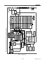
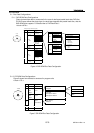
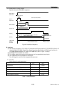
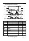
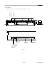
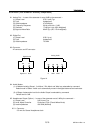
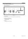
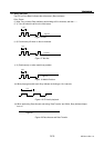
6.2.4.Timing of Host Interface (Ultra DMA )
Figure 12 shows the Host Interface Ultra DMA word Timings
DMARQ
DMACK-
STOP
DMARDY
STROBE
tMLI
tUI
tACK
tFS
tENV
tZAD
tZIORDY
t2CYC
tRP
tRFS
tLI
tACK
tDVS
tDVH
CRC
tDVHtDVS
tDVHtDVStDVHtDVS
tCYC
tCYC
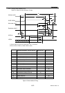
DD (15:0)
Sender
STROBE
tZAD
tZIORDY
tDS tDH
CRC
tDH
tDStDH
tDS
tDHtDS
DD (15:0)
Recipient
t2CYC
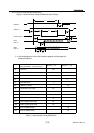
In all timing diagrams, the low line indicator negated, and the upper line indicators asserted.
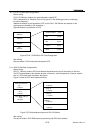
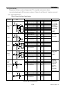
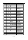
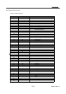
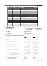
Ultra DMA Mode 2
Timing parameters min (ns) max (ns)
Min time (ns) Max time (ns)
t2CYC
Typical Sustained Average Cycle time 120
Two cycle time (from rising edge to next rising edge of
from falling edge to next falling edge of STROBE)
117
tCYC Cycle time allowing 55
tDVS Data valid Setup time 34
tDVH Data valid Hold time 6
tUI Unlimited Interlock time 0
tACK Setup and Hold Time for DMACK- 20
tENV Envelope time 20 70
tZAD Minimum Delay time for Driver 0
tZIORDY Minimum time for DMACK- 20
tFS First STROBE time 0 170
tRFS Ready-to-Final STROBE time 50
tRP Ready-to-Pause time 100
tLI Limited Interlock time 0 150
tMLI Interlock with minmum 20
tDS Data setup time (at recipient) 7
tDH Data hold time (at recipient) 5
Figure 12 Host Interface Timing (Ultra DMA)