


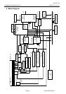

OD-A017-02
TOSHIBA DVD-RAM SD-W1111 ‘99/06/26 Version 1.0
Page 22 Product Specification
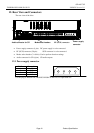
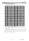
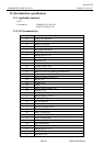
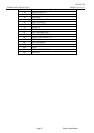
12.2 I/F connector (SCSI connector)
12.2.1 Pin No. table of connector terminal
Pin Signal Pin Signal
1 Ground 2 DB0
3 Ground 4 DB1
5 Ground 6 DB2
7 Ground 8 DB3
9 Ground 10 DB4
11 Ground 12 DB5
13 Ground 14 DB6
15 Ground 16 DB7
17 Ground 18 DBP
19 Ground 20 Ground
21 Ground 22 Ground
23 Ground 24 Ground
25 Open 26 TERMPWR
27 Ground 28 Ground
29 Ground 30 Ground
31 Ground 32 ATN
33 Ground 34 Ground
35 Ground 36 BSY
37 Ground 38 ACK
39 Ground 40 RST
41 Ground 42 MSG
43 Ground 44 SEL
45 Ground 46 C/D
47 Ground 48 REQ
49 Ground 50 I/O
*Notes 1) the low level of all signals returns TRUE.
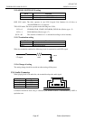
Use Hirose Electronics Co. HIF 3BB-50DA-2.54R, Molex 5320-50AT2 or equivalent one for the
connector on cable side.
The voltage is added on the TERMPWER signal from the internal side of a drive. The maximum
power supply current from internal side of a drive is 1.1A. If the current exceeds this level, the
internal current limiter operates to stop the voltage addition. After the cause of excess current is
removed, the signal returns to the original status.