


6 F 3 B 0 3 6 4
131
6.2 Indications of the 7
-
Segment LED
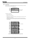
The 7-segment LED (NA/ERROR) on the front panel of the DN211 is used for indicating a node
address/error code.
When the DN211 is normally transmitting with slave devices, the local station node address (value
set by the rotary switch on the side panel of the module) is displayed.
Moreover, if one of the following troubles occurs, the 7
-
segment LED indicates the state of the
module or the network.
• When the DN211/network/slave device is encountering trouble
• When an error occurs with requests from the T2/T2E/T2N
• When the DN211 is downed
This LED is blinking the local station node address while creating a scan list at the step of setting
slave device parameters.
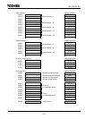
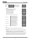
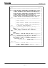
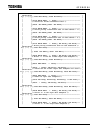
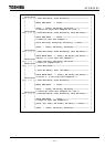
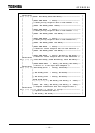
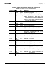
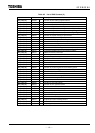
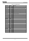
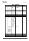
Table 6.2 and Table 6.3 describe combinations in the 7-segment LED for module status / network
status, and their meanings. The mark "⇔" in the tables indicates alternative display of indications
on both sides.
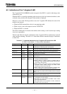
Table 6.2.7 Combined Indications of the 7
-
segment LED and 2-Color LED
M: DN211 node address S: Slave device node address
7
-
segment LED MS NS Description
Not lit Not lit Not lit No power is supplied to the T2/T2E/T2N
Initialization is underway after reset request.
M lighting Not lit Not lit Indicates standby mode
(Just after switching ON the power; after reset request)
M blinking Not lit Not lit In the processing of setting slave device parameters
M lighting Green
lighting
Green
lighting
Is engaging in normal transmission (both module and
network have no trouble)
70 ⇔ M Green
lighting
Red
lighting
The DN211 detected an duplicated node address with a
slave device.
72 ⇔ S Green
lighting
Red
blinking
1) When the response from a slave device ceased
during normal transmission
2) When setting no polling mode to enabled state at
operation mode setting though polling mode devices
are found in the scan list
3) When setting no bit strobe mode to enabled state at
operation mode setting though bit strobe mode
devices are found in the scan list
4) When setting slave device parameters, reception data
size or scan type is different from the actual one.
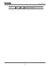
73 ⇔ S Green
lighting
Red
blinking
When setting slave device parameters, the vendor ID,
product type, or product code is different from the actual
one.
75 ⇔ M Green
lighting
Red
blinking
No slave device is found on the network when starting
transmission (this indication only)
75 ⇔ M Green
lighting
Green
blinking
1) When run mode is requested without setting the
parameters of a slave device
* This state can occur before the DN211 and a slave
device start transmission.
If this state lasts for 30 seconds or more, check the
parameters of the slave device.