


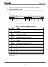


6 F 3 B 0 3 6 4
76
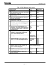
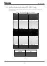
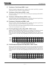
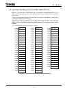
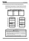
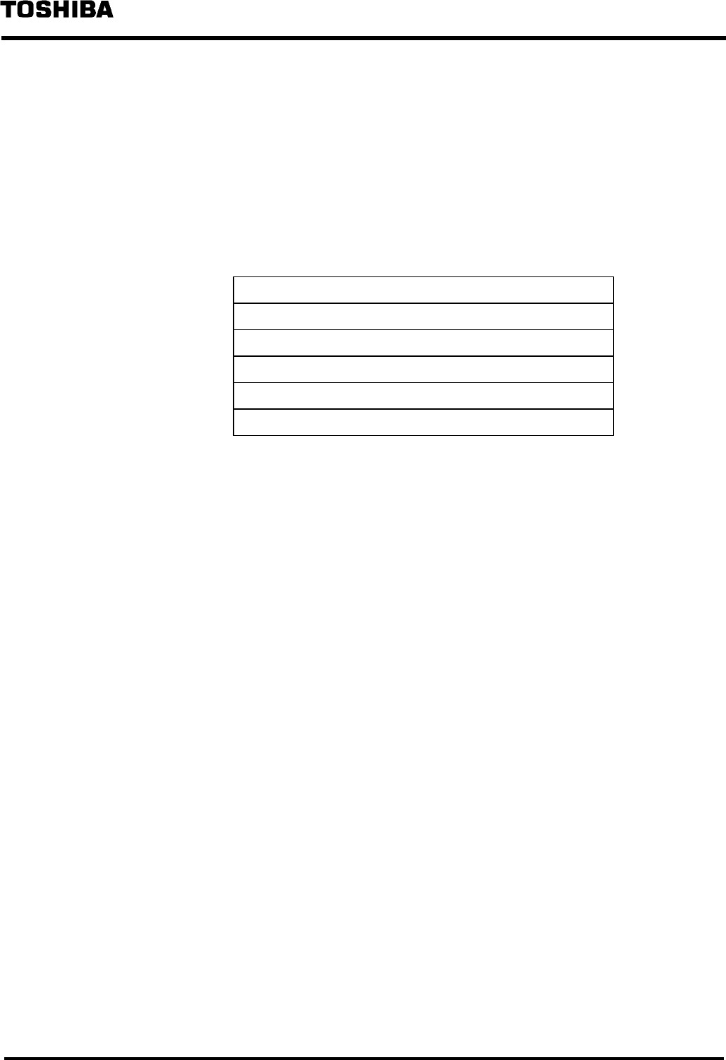
Example) Input/output data setting information for node address = 1
• Input data offset indicates the offset address (in bytes) from the top (0000H) of input
data area.
• Output data offset indicates the offset address (in bytes) from the top (0080H) of
output data area.
• There are no items for the offset of bit strobe output data and for the number of bytes
because of the bit strobe output data area.
Table 4.10 Input/Output Data Setting Information for Node Address = 1
0111H Bit strobe input data offset
0112H Number of bit strobe input data bytes
0113H Polling input data offset
0114H Number of polling input data bytes
0115H Polling output data offset
0116H Number of polling output data bytes
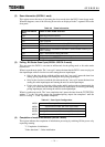
(14) The Local Station Node Address (010AH:1 word)
The hexadecimal node address of the local station, specified with the rotary switch on the side face
of the module, is stored (00H - 3FH).
(15) The Network Communication Rate (0109H:1 word)
The network communication rate, set with the DIP switch on the front panel, is stored.
00H: Unassigned (setting disabled)
01H: 500kbps
02H: 250kbps
03H: 125kbps
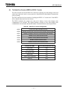
(16) The Operation Mode on Busoff Occurring (0108H:1 word)
The DN211's operation mode setting is stored when the DN211 detects busoff state of the local
station.
00H: When busoff is detected, the module will be set to standby mode, followed by the
initialization of the CAN controller.
The procedure for resuming transmission is the same for starting ordinary
transmission. Chapter 5 describes the transmission start procedure.
01H: When busoff is detected, the operation mode of the module is left intact, and the
CAN controller is initialized, followed by resuming communication, if possible.
(17) Yes/No of Supplying the Network Power (0107H:1 word)
The supply mode of the network power is stored.
00H: Network power normal
01H: Network power abnormal