


6 F 3 B 0 3 6 4
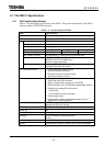
40
3. Preparation for Operation (hardware)
3.1 DN211 Setting Flowchart (hardware)
DANGER
1. Configure an emergency-stop circuit, interlock circuit, and/or other similar safety circuits
outside the PC and DN211.
If the PC or DN211 gets failed or malfunctioned, it can cause an accident which will lead to
bodily injury and/or mechanical damage.
CAUTION
2. Secure the safe environment before executing program modification, forcible output, RUN, or
HALT instruction during operation. An operational mistake can cause mechanical damage or
accident
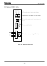
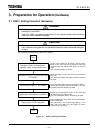
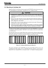
The following flowchart shows the DN211 setting.
Start
End
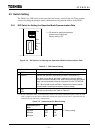
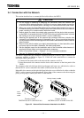
Setting your DN211's node address /
operation mode / communication rate
Set the node address for the DN211 with the rotary
switch on the side. Also set the operation mode and
communication rate with the DIP switch on the front
panel.
See '3.2 Switch Setting" for detail.
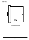
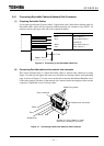
Mounting the DN211 on the I/O slot of the
T2/T2E/T2N
Mount the DN211 into the I/O slot of the T2/T2E/T2N
base unit.
See "Mounting module" in the Main Unit User’s Manual
for detail.
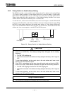
Connecting the DN211 to the network
Using the network side connector (attached to DN211),
connect the DeviceNet cables to the DN211. See "3.4
Connection with the Network" for detail.
Supplying the network power to the DN211
Supply the communication power for the DeviceNet
devices through the network cable.
See "3.5 The Network Power / Grounding" for detail.
Supplying the T2/T2E/T2N power
After completing the above work, switch ON the power
of the T2/T2E/T2N.
See "Grounding" and "Power-supply Wiring" in the
Main Unit User’s Manual for the details of power-
supply wiring / grounding.
Figure 3.1 DN211 Setting Flowchart