


- 11 -
CONTROL REFERENCE GUIDE
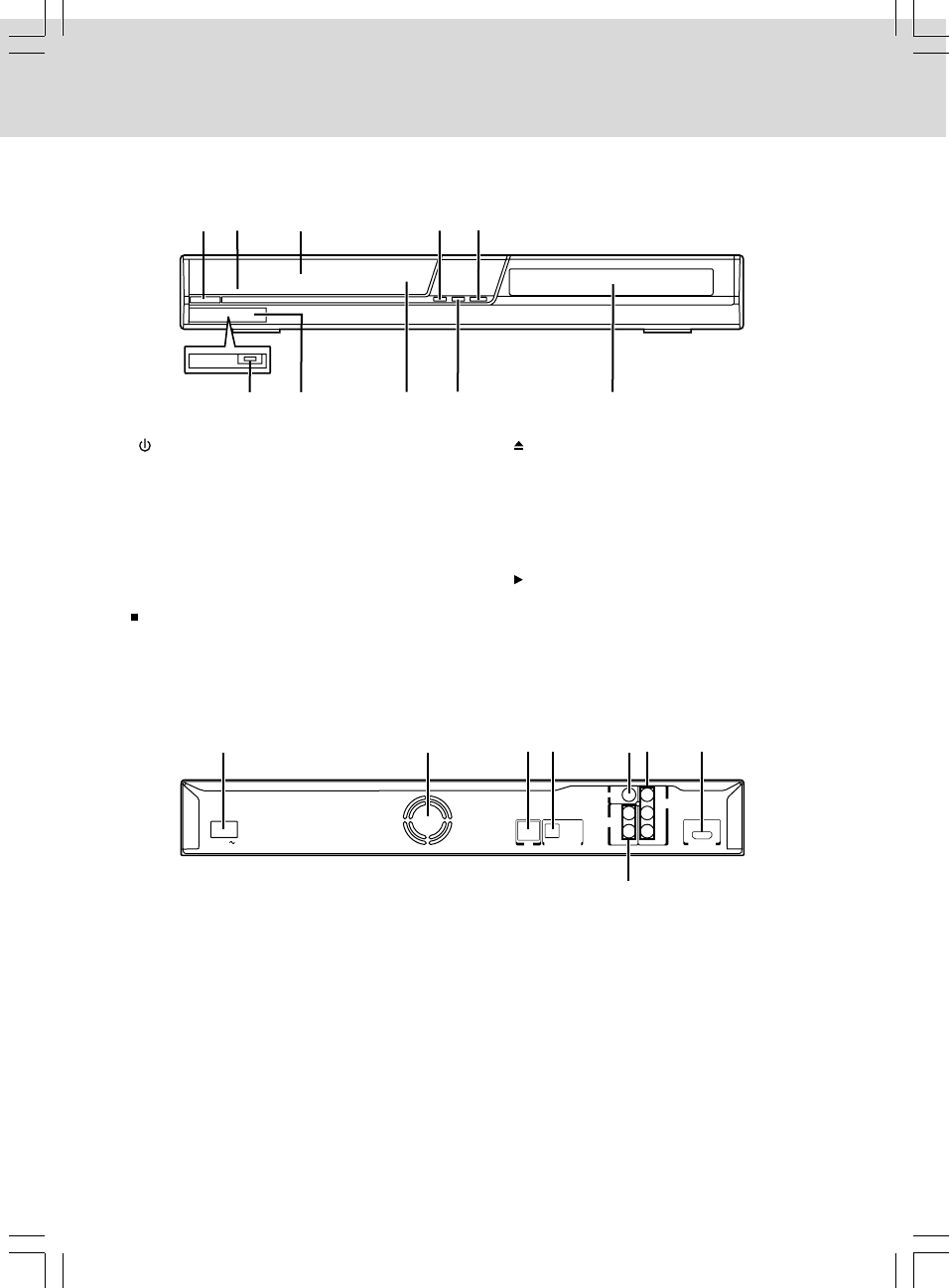
Unit
(Front View)
Unit
(Rear View)
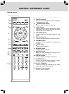
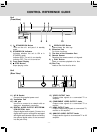
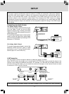
11) AC IN Socket
Connect the supplied power cord.
12) Ventilation Fan
13) LAN port
Use this to connect to a network with an
always-on broadband connection.
14) DIGITAL AUDIO OUTPUT BITSTREAM/
PCM OPTICAL Jack
Outputs digital audio signals. Connect to a
digital audio input on an amplifier equipped
with digital audio decoder. When connecting
the optional digital cable, fit the connector
into the jack firmly.
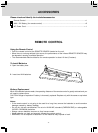
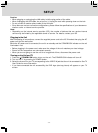
1) I/ STANDBY/ON Button
Turns on the unit and puts it in standby
mode.
2) STANDBY/ON Indicator
Indicates whether the unit is ON or in
STANDBY mode.
Indicator RED: The unit is on standby.
Indicator OFF: The unit is turned on.
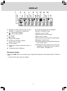
3) Front Panel Display
4) STOP Button
Stops playing a disc.
5) OPEN/CLOSE Button
Opens/closes the disc tray.
6) Extension Port
For future functions.
7) The door of the Extension Port
8) Remote Sensor
Receives the remote control unit signals.
9) PLAY Button
Starts or resumes playback of a disc.
10) Disc Tray
Loads a disc into the disc drive.
HDMI OUTPUT
COMPONENT
VIDEO OUTPUT
VIDEO OUTPUT
ANALOG AUDIO
OUTPUT
BITSTREAM
/PCM
OPTICAL
DIGITAL AUDIO OUTPUT
LAN
L
RP
R
P
B
Y
AC IN
11
12
13
14 15
17
16
18
15) VIDEO OUTPUT Jack
Outputs video signals to a connected TV or
amplifier.
16) COMPONENT VIDEO OUTPUT Jacks
Outputs video signals to a connected TV or
monitor.
17) HDMI OUTPUT Jack
Outputs video/audio signals to connected TV,
monitor or AV amplifier.
18) ANALOG AUDIO OUTPUT Jacks
Outputs audio signals to a connected TV or AV
amplifier.
1
2
3
6
7
4
5
8
10
9