Vidikron VL-37 Owner’s Operating Manual 5
2.1
DView at a Glance
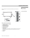
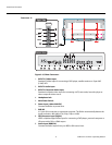
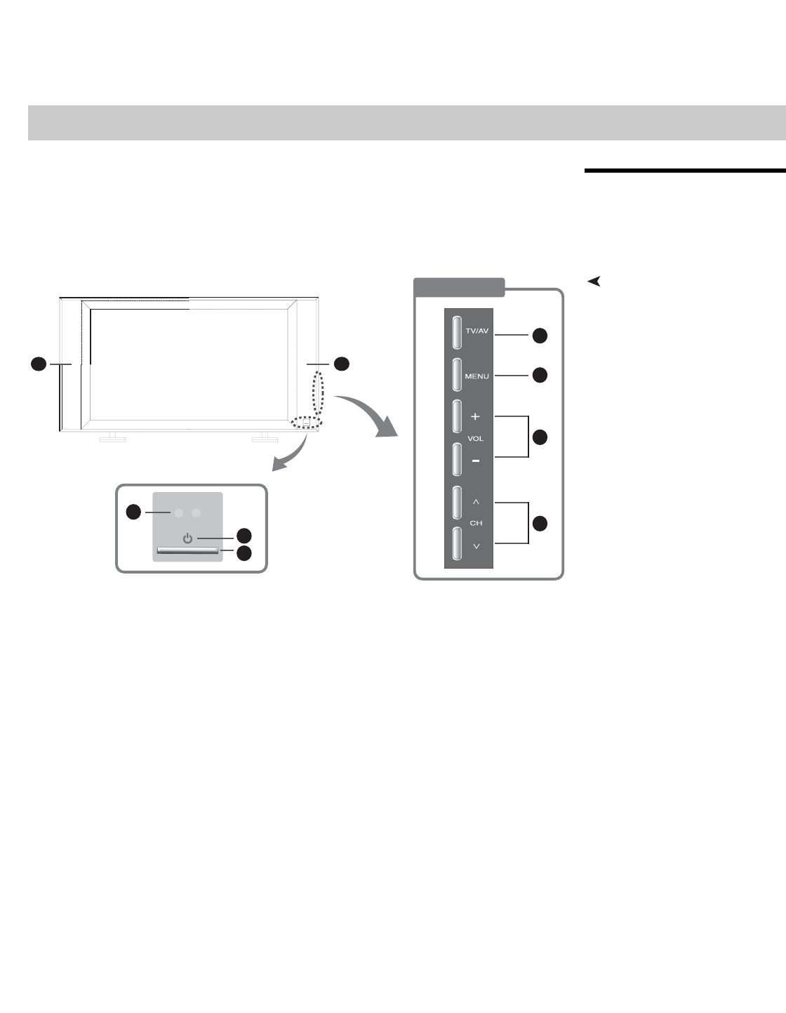
Figure 2-1 and Figure 2-2 show the locations of the DView controls, indicators and
connectors.
Controls and Indicators
Figure 2-1. DView Controls and Indicators
1. TV/AV Button (Input Source Selection)
2. MENU Selection Button
3. Volume Adjustment Buttons
4. Channel Selection Buttons
5. Remote Control Sensor
6. Power Indicator
Lights red to indicate that the DView is in standby mode; lights green to indicate normal
operation; flashes green when the DView receives a signal from the remote control.
7. Power Button
8. Speakers
2Controls and Functions
Right Side
1
2
3
4
6
7
5
8
8


