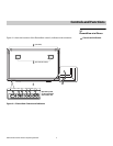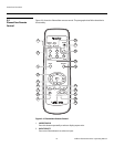
Controls and Functions
Vidikron PlasmaView Owner’s Operating Manual 9
PRE
L
IMINAR
Y
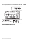
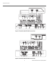
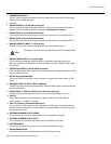
1. COMBINATION IN/OUT
Used to control multiple PlasmaView monitors collectively. Use a 6-pin, mini-DIN cable
(all pins wired straight-through).
2. Not used.
3. AUDIO (OUTPUT) (3.5-mm stereo mini jack)
Used to output the audio of the selected source component connected to the plasma
display to an AV amplifier or similar component. The output level is fixed.
4. AUDIO (INPUT 1) (3.5-mm stereo mini jack)
Connect this jack to the audio output connector(s) of the device connected to INPUT 1.
5. AUDIO (INPUT 2) (3.5-mm stereo mini jack)
Connect this jack to the audio output connector(s) of the device connected to INPUT 2.
6. ANALOG RGB OUT (INPUT 1) (15-pin D-Sub)
If desired, connect this output to the RGB input of a second display device.
7. ANALOG RGB IN (INPUT 1) (15-pin D-Sub)
For connecting components that have RGB or component output jacks such as a
personal computer or external DTV decoder (a break out cable is needed for BNC-type
connection).
8. DIGITAL RGB (INPUT 2) (DVI-D, HDCP-compliant)
VESA-standard digital video input from a personal computer, or digital video from a DVD
player or HD set-top box.
9. RS-232 (9-pin, female D-Sub)
Connect the RS-232 output from your computer or automation/control system to this
input.
10. DVI VIDEO (INPUT 5) (DVI-D, HDCP-compliant)
This DVI input will process digital video 480p, 720p and 1080i signals (computer rates are
not recommended).
11. AUDIO (INPUT 5 / INPUT 4 / INPUT 3) (3.5-mm stereo mini jack)
Used for external audio input from video sources connected to Inputs 5, 4 and 3.
12. INPUT 4
Interlaced or progressive component input (480p to 1080i, 50 or 60 Hz; 480i not
recommended – use INPUT 3 instead).
13. INPUT 3 (S-Video or Composite Video Input)
For connecting a VCR, camcorder, laser disc player or DVD player. Use the push button
between the two connectors to select S-Video or Composite Video on Input 3 (only one
can be active at a time).
14. EXTERNAL SPEAKER OUTPUT (RIGHT)
For connection of an external right speaker with an impedance of 6 ohms.
15. EXTERNAL SPEAKER OUTPUT (LEFT)
For connection of an external left speaker with an impedance of 6 ohms.
16. AC POWER INPUT
Connect the PlasmaView to power here, using the included power cord.
17. MAIN POWER SWITCH
Connects or disconnects the PlasmaView from the AC power source.
This output is not active when the PlasmaView is off or in standby mode.
Note


