


VIZIO GV47L FHDTV20A User Manual
Version 4/23/2008 13
www.VIZIO.com
Right Portion
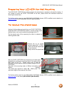
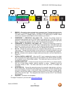
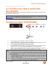
8. RGB PC – Connect the video and audio from a computer here. The blue color band on the
rear of the TV indicates this connection. To supply the audio signal either a straight 1/8” to
1/8” stereo cable or a Y-adapter cable (L+R audio to 1/8” stereo plug) is needed. Please
consult your computer manual before to find out what is your choice.
9. COMPONENT 1 (YPb/CbPr/Cr with Audio L/R) – Connect the primary source for
component video devices such as a DVD Player or set top box here. From left to right, use
green for Y, blue for Pb (or Cb), red for Pr (or Cr), white for left audio and red for right audio
inputs. The green color band on the rear of the TV indicates this connection.
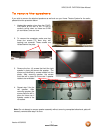
10. COMPONENT 2 (YPb/CbPr/Cr with Audio L/R) – Connect the secondary source for
component video devices such as a DVD Player or set top box here. From left to right, use
green for Y, blue for Pb (or Cb), red for Pr (or Cr), white for left audio and red for right audio
inputs. The purple color band on the rear of the TV indicates this connection.
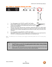
11. AV1 IN – Connect the secondary source for composite video devices, such as a DVD or
video game. Connect the audio output of the source into L+R audio connectors (red and
white connectors). The yellow color band on the rear of the TV set indicates this connection.
12. DTV/TV – Connect to an antenna or digital cable (out-of-the-wall, not from Cable Box) for
Digital TV.*
13. OPTICAL DIGITAL AUDIO OUT – When the DTV input is selected for viewing, the digital
audio associated with digital programming will be available on this SPDIF Optical connector
for connection to your home theatre system. The white color band on the rear of the TV
indicates this connection.
14. ANALOG AUDIO OUT – Connect the audio from the LCD HDTV to an external device,
such as a home theatre system, external amplifier or stereo. Speakers cannot be
connected directly to here. The white color band on the rear of the TV indicates this
connection.
15. AV2/S-VIDEO IN – Connect the secondary source for composite video devices, such as a
DVD or video game. Connect the audio output of the source into L+R audio connectors (red
and white connectors). Keep in mind that S-Video connections are only images signals;
therefore, a set of audio cables is needed to hear the sound. The S-Video, if connected, will
take priority over this input. The orange/red color area on the rear of the TV set indicates
this connection.
16. SPEAKER – Connection for left speaker.
* For digital TV stations in your area visit www.antennaweb.org
9
12
13
8
15
10
11
14
15