


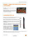
VIZIO P50 HDTV20A User Manual
Version 12/6/2007 11
www.VIZIO.com
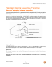
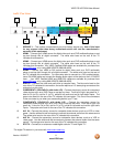
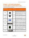
Left Portion
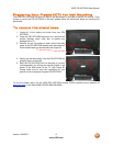
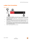
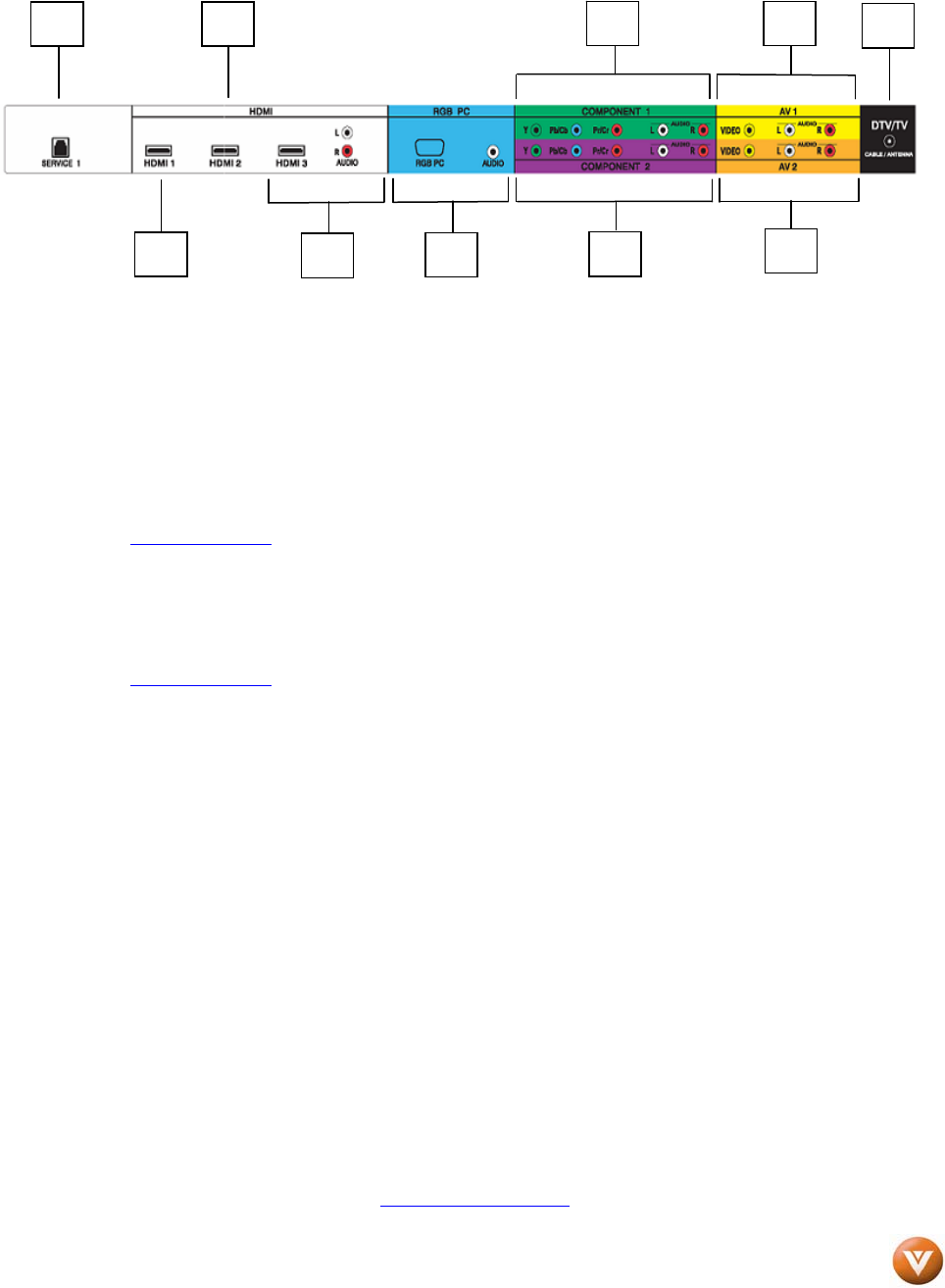
5. SERVICE 1 – This custom communication port is for factory service only. Use of this input
for any purpose other than factory authorized service will void the manufacturer’s
warranty of this equipment.
6. HDMI1 – Connect your HDMI source for digital video such as a DVD multimedia player or set
top box through this all digital connector. The white color band on the rear of the TV
indicates this connection.
7. HDMI2 – Connect your HDMI source for digital video such as a DVD multimedia player or set
top box through this all digital connector. The white color band on the rear of the TV
indicates this connection. Your VIZIO Certified HDMI cables are available for purchase from
www.VIZIO.com
or by calling 888-VIZIOCE (888-849-4623).
8. HDMI3 – Connect your HDMI or DVI source for digital video such as a DVD multimedia
player or set top box through this all digital connector. The white color band on the rear of
the TV indicates this connection. For users who want to connect to a DVI enabled device,
use a DVI-HDMI cable and connect the Analog Audio output of the device to the L+R AUDIO
here. . Your VIZIO Certified HDMI and HDMI-DVI cables are available for purchase from
www.VIZIO.com
or by calling 888-VIZIOCE (888-849-4623).
9. RGB PC – Connect the video and audio from a computer here. The blue color band on the
rear of the TV indicates this connection; the audio requires a 1/8” stereo plug connector at the
end going into this input.
10. COMPONENT1 (YPb/CbPr/Cr with Audio L/R) – Connect the primary source for component
video devices such as a DVD Player or set top box here. From left to right, use green for Y,
blue for Pb (or Cb), red for Pr (or Cr), white for left audio and red for right audio inputs. The
green color band on the rear of the TV indicates this connection. This row of five connectors
is the one closer to you when you are standing behind your TV set.
11. COMPONENT2 (YPb/CbPr/Cr with Audio L/R) – Connect the secondary source for
component video devices such as a DVD Player or set top box here. From left to right, use
green for Y, blue for Pb (or Cb), red for Pr (or Cr), white for left audio and red for right audio
inputs. The purple color band on the rear of the TV indicates this connection.
12. AV1 IN – Connect the primary source for composite video devices, such as a VCR or video
game. Use the white and red connectors to connect the external audio from the same source.
The yellow color band on the rear of the TV indicates this connection.
13. AV2 IN – Connect the secondary source for composite video devices, such as a VCR or
video game. Use the white and red connectors to connect the external audio from the same
source. The orange color band on the rear of the TV indicates this connection.
14. DTV/TV – Connect to an antenna or cable/digital cable for TV and Digital TV.*
* For digital TV stations in your area visit www.antennaweb.org
.
11
5
10
13
12
6
9
7
8
14