


9
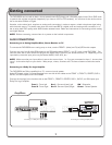
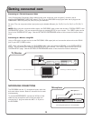
Connecting to a TV with Component Video
Using 3 appropriate Component Video cables (usually color coded red, blue and green), connect a set of
plugs to the COMPONENT VIDEO OUT jacks (Y/Cb/Cr) on the DVG-399K and plug the other set of plugs to the
COMPONENT VIDEO IN jacks (Y-U/Cb-V/Cr) on your television.
On some TVs, the component video input jacks may be labeled differently (i.e. Pr/Pb/Y or Cr/Cb/Y or R-Y/B-Y/Y
etc.).
NOTE: When using the component video output, the DVG-399K’s video mode must be set to “P-SCAN YPBPR” in the
SYSTEM SETUP screen. You can access this screen by pressing SETUP on your remote. The “VIDEO” option can be
found in the “SYSTEM SETUP” page. See the SETTING UP PREFERENCES section of this manual for further instruc-
tions.
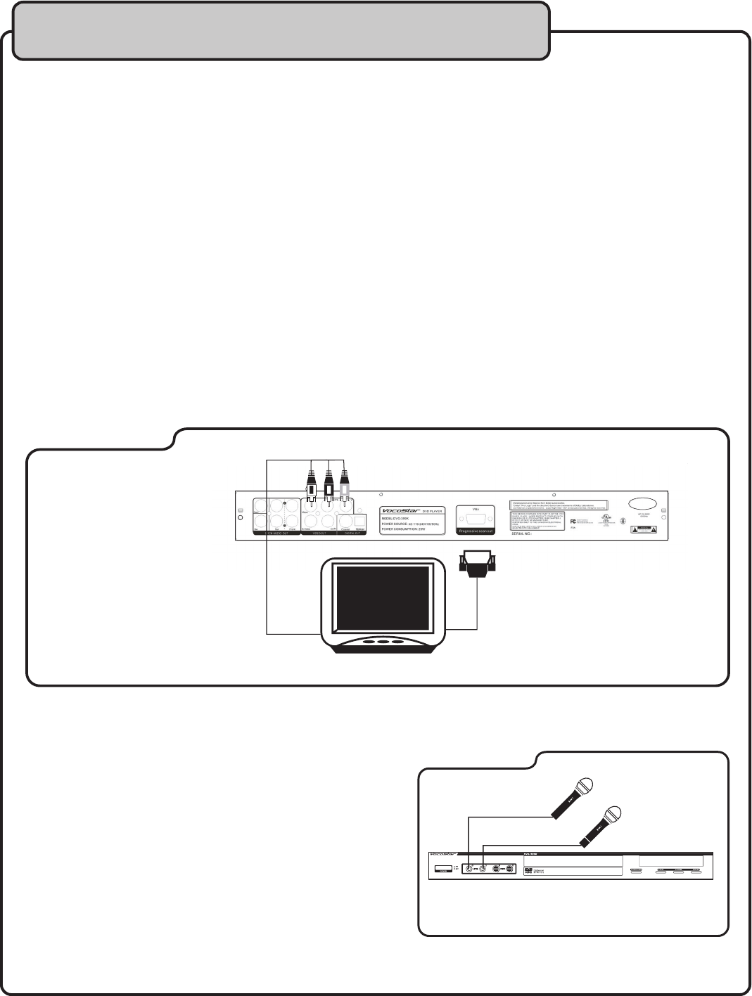
Connecting to a Monitor using VGA
Using a VGA cable, connect one end to the DVG-399K’s VGA output jack and connect the other end to the VGA IN
jack on your HDTV/VIDEO monitor.
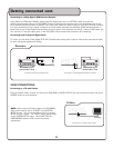
NOTE: When using the VGA output, the DVG-399K’s video mode must be set to “PC-VGA” in the SYSTEM SETUP
screen. You can access this screen by pressing SETUP on your remote. The “VIDEO” option can be found in the
“SYSTEM SETUP” page. See the SETTING UP PREFERENCES section of this manual for further instructions.
MICROPHONE CONNECTIONS
The DVG-399K has two ¼” microphone inputs, each with
their own volume control. Both mic channels can be used
simultaneously.
To connect MICROPHONES, connect the XLR-end of the
cable into the microphone until it locks into place and
connect the ¼” plug into either the MIC 1 or 2 jack on
the DVD-399K.
Getting connected cont
Connecting to a Monitor using VGA
Connecting to a TV with Component Video
TV/Monitor
DVD/CD+G/VCD/MP3/CD/PHOTO-CD KARAOKE PLAYER WITH DIGITAL KEY CONTROL
OF
F
ON
OFF
ON
Connecting Microphones to the DVG-399K
Microphone
Microphone 1
Television/Monitor
Microphone 2