800057-02 Rev. A Page 1 of 11 May 24, 2003
DTV742 Installation Quick Start Guide
The Wegener Model DTV742 8VSB 4-Channel Multiplexor receives VHF/UHF broadcast HDTV signals and provides output ASI
streams for connection to cable system QAM modulators. This guide provides information for setting up and operating the DTV742.
Additional information may be found on the Wegener web site at www.wegener.com/
In addition to this guide, your box should include:
1. DTV742 8VSB 4-Channel Multiplexor
2. Power cord 3. UL safety sheet
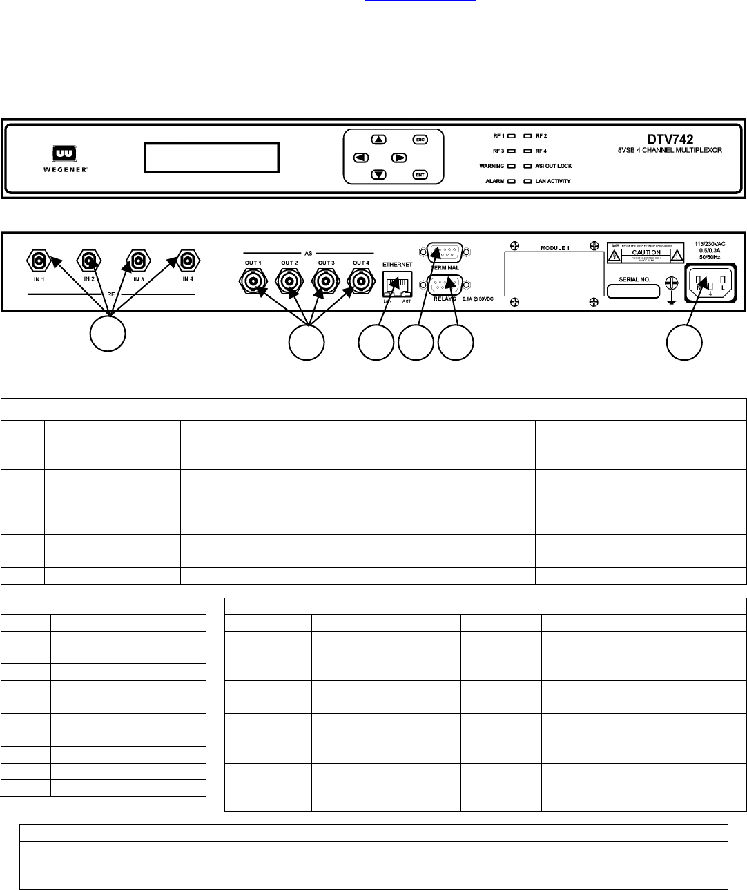
Front and Rear Panel View
Connector/Pin-out Information
Rear-Panel Connector Descriptions
Ref
Connector
Designation Type Signal Name Description
1 RF In 1, 2, 3, & 4 Type F RF IN 1, RF IN 2, RF IN 3, & RF IN 4 From VHF/UHF Antenna
2 ASI Out 1, 2, 3, & 4 BNC
ASI OUT 1, ASI OUT 2, ASI OUT 3,
& ASI Out 2
To Advanced Cable Channel
Groomer, DTV700, or ASI Mux
3 Ethernet RJ-45 jack Ethernet_In & Out
To LAN – for Web Interface
Control
4 Terminal DB-9 female RxD (output) & TxD (input) To Local Terminal
5 Relays DB-9 female Alarm, Warning, & Contact Closures To Alarm Monitoring
6 115/230 VAC IEC receptacle AC Line In To AC Power Outlet
Status Relays Signals(Ref 4) LED Indicator Descriptions
Pin # Function LED Description LED Description
9
Close on Alarm or
power failure
4Alarm COM
RF 1
ON – Tracking carrier
OFF – No carrier
RF 2
ON – Tracking carrier
OFF – No carrier
8 Close on Warning
3 Warning COM
RF 3
ON - Tracking carrier
OFF – No carrier
RF 4
ON – Tracking carrier
OFF – No carrier
6 Open on Warning
1 Not used
7 Open on Alarm
WARNING
ON – See LCD / web
browser for details
OFF – No Warnings
ASI OUT
LOCK
ON – ASI output active
OFF – No ASI output
2 Not used
5Ground
ALARM
ON – See LCD / web
browser for details
OFF – No alarms
LAN
ACTIVITY
BLINKS – parameter is being
changed via browser or SNMP
Program and PSIP Processing
The unit tunes and demodulates 8VSB ATSC broadcast signals which are converted to ASI output transport
streams. Selected programs and PSIP data received are passed through to the output ASI ports. PSIP
processing may be enabled or disabled.
1
2
5
4 6
3


