


6
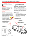
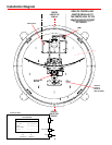
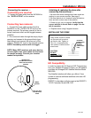
Installation Diagram
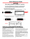
Control Box detail
LNBF
RECEIVER
P4
ELEVATION
P3
AZIMUTH
(#1 represents Switch DOWN; #0 represents Switch up)
Sat. Rcvr. Switch Set Position
....................... ....1 2 3 4 5 6 7 8
DISH NETWORK ....................... .......0 ... 0 ....0 ... 1 ....0 ...0 ....1 ...1
DIRECTV ....................................0 ... 0 ....0 ...0 ....0 ...0 ....0 ...1
(FACTORY PRESET)
ExpressVu ..................................0 ...1 ....0 ...1 ....1 ...0 ....1 ... 1
Model MV3500A
Control Unit
ELEVATION
MOTOR
LNBF
SiDeS of ConTrol UniT
MUST Be PArAllel To
The CenTer line of The
vehiCle AnD fACe fronT
or reAr of vehiCle.
CenTer
line of The
vehiCle
GPS ANTENNA
(RoadTrip SDi In-Motion
models ONLY)
CenTer
line of The
vehiCle
Used for
Second
Receiver
(Not Included)
of vehiCle.