


Pinch point (labeled)
FIGURE 2. Pinch points
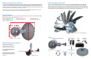
Mount Base with 30’ Power/Control Cable
Mounting Screw (20)
Reflector
30’ Gray Coax Cable
Interface Box
Power Supply
24” AC power cord
Cable Entry Plate
5/16” Reflector Bolt (4)
5/16” Reflector Nut (4)
Interface Box
Pinch point (labeled)
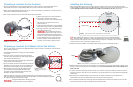
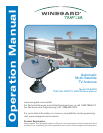
FIGURE 1. Dimensions of SK-SWM3
44″
34″
23.5″
24″
21″
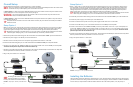
FIGURE 3. Range of motion for TRAV’LER SWM antenna
Splitter21V SWM Power Inserter
1
2
Before Installing the Antenna
You have selected the Winegard
®
TRAV’LER
®
automatic multi-satellite TV antenna. The TRAV’LER antenna will deliver
the ability to view multiple satellites at the same time with unmatched signal strength, the lowest travel height on
the market, maximum HD capabilities and easy to use functionality—just like you get at home. This manual provides
important information on the installation and operation of your TRAV’LER antenna on an RV. Please take time to read
the manual in its entirety before installing or operating your antenna.
Follow the instructions on this side of the manual if installing the TRAV’LER DIRECTV SWM Slimline antenna. For
operation instructions, follow the instructions on the reverse side of the manual.
Specifications
Depending on location and receiver type, the following satellites can be accessed with the TRAV’LER DIRECTV SWM
Slimline antenna during automatic operation: 99°, 101°, 103°.
Safety Recommendations
Do not attempt to install this
system in the rain or under any wet
conditions. Moisture may affect
electronics and void your warranty.
Do not paint this antenna. Painting
the TRAV’LER antenna will void
your warranty.
Pay attention to the pinch points as
the antenna raises. The pinch points
should be labeled on the antenna
(see fig. 2).
Clearance Requirements
The arm of the TRAV’LER antenna extends 33” from the center of the base and may operate only 10” above the
surface to which the TRAV’LER antenna is mounted. To ensure you have adequate clearance for the TRAV’LER
antenna to safely operate, check that there are no obstructions taller than 10” within 33” of the center of the base.
Also, check that there are no obstructions (such as tree limbs) above the antenna that will prevent it from raising.
At its highest point, the antenna will extend to 37.5” above the roof to which it is mounted (see fig. 3).
Parts
Height of assembled unit: 9.75”
Width of assembled unit: 34”
Length of assembled unit: 44”
Width of mount base: 21”
Length of mount base: 24”
Unit Weight: 53 pounds
Shipping Weight: 74 pounds