


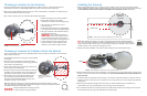
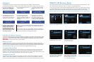
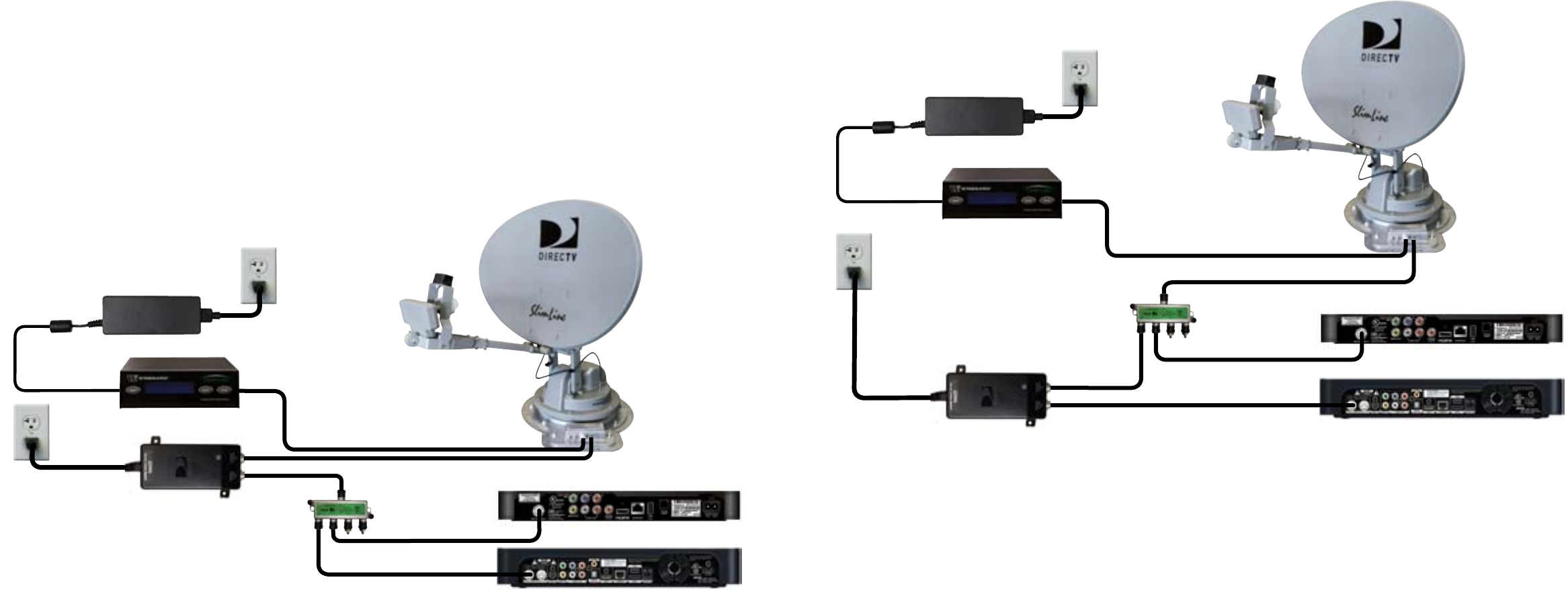
FIGURE 8. Setup Option 1 with fully assembled antenna
5
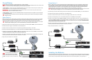
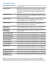
FIGURE 9. Setup Option 2 with fully assembled antenna
DVR Receiver
Non-DVR Receiver
Interface Box
Power Supply
Splitter
6
Overall Setup
Choose between Setup Option 1 and Setup Option 2 to connect all cables.
NOTE
Only port C should be used for making connections to the mount base. Multiple receivers will connect to the
mount base via the provided splitter; ports A and B will not be used.
In Setup Option 1, a cable runs from the TRAV’LER antenna to the power inserter and from the power inserter to the
splitter; cables then run from the splitter to each receiver (see fig. 8).
WARNING
The power inserter should not be mounted on the roof of the vehicle. The power inserter must
always be installed inside the vehicle.
In Setup Option 2, a cable runs from the TRAV’LER antenna to the splitter and from the splitter to the power inserter
and receiver(s) (see fig. 9).
TIP
The splitter can be mounted on the roof of the vehicle. However, the power inserter must always be installed
inside the vehicle.
Setup Option 1
1. Drill a 1″ hole in the roof, and push the power/control cable and coax cable (running from port C of the mount base)
through the hole. Place the supplied cable entry plate over the hole and cables, and screw the plate in place using
eight of the supplied mounting screws. Seal the plate and screw holes with approved sealant (not included).
TIP
Depending on the length of the cable on the roof, you may need to use cable clamps between the unit and the
cable entry plate. Clamping every 12–16” should eliminate any unnecessary cable movement.
2. Connect the power/control cable running from the mount base to the “DC OUT/ANT. COMM.” port of the interface box.
3. Connect the power supply to the “DC IN” port of the interface box.
4. Connect one end of the AC power cord to the power supply and the other end to a 110V outlet.
5. Connect a coax cable running from port “C” of the mount base to the “POWER TO SWM” port of the power inserter.
6. Connect a coax cable from the “SIGNAL TO IRD” port of the power inserter to the “In from SWM” port of the splitter.
Terminate unused splitter outputs with a 75 ohm termination cap.
7. Connect a coax cable from the splitter to each receiver. The receiver(s) should already be connected to the TV(s). Note
that the provided coax cable only includes a connector on one end.
8. Plug in the power inserter to a 110V outlet.
Setup Option 2
1. Drill a 1″ hole in the roof, and push the power/control cable through the hole. If you would like any cables running
from the splitter to enter the roof at this same point, push the cable(s) through this hole. Place the supplied cable
entry plate over the hole and cables, and screw the plate in place using eight of the supplied mounting screws. If
making multiple holes for cables to run from the splitter to each receiver, push the cables through the respective
holes. Seal the plate, screw holes, and other drilled holes with approved sealant (not included).
TIP
Depending on the length of the cable on the roof, you may need to use cable clamps between the unit and the
cable entry plate. Clamping every 12–16” should eliminate any unnecessary cable movement.
2. Connect the power/control cable running from the mount base to the “DC OUT/ANT. COMM.” port of the interface box.
2. Connect the power supply to the “DC IN” port of the interface box.
3. Connect one end of the AC power cord to the power supply and the other end to a 110V outlet.
4. Connect a coax cable from port “C” of the mount base to the “In from SWM” port of the splitter.
5. Connect a coax cable from the “POWER TO SWM” port of the power inserter to the “Out 1” port of the splitter, and
connect the “SIGNAL TO IRD” port of the power inserter to a receiver. The “Out 1” port of the splitter is the only port
that is power passive; therefore, the power inserter must be connected to this port of the splitter. Terminate unused
splitter outputs with a 75 ohm termination cap.
6. Connect a coax cable from the splitter to each receiver. The receiver(s) should already be connected to the TV(s). Note
that the provided coax cable only includes a connector on one end.
7. Plug in the power inserter to a 110V outlet.
Installing the Reflector
Once the sealant around the cable entry plate has begun to cure, check that there is nothing above the unit that might
prevent the antenna from raising. Follow the instructions on the next page to raise the antenna for reflector installation.
In some cases you may be able to install the reflector with the unit in the stowed position; if so, skip to step 3.
NOTE
If hooking up the antenna to only one
receiver, the splitter is not needed,
but the power inserter must still be installed.
DVR Receiver
Non-DVR Receiver
Power Inserter
Interface Box
Power Supply
Splitter
Power Inserter