


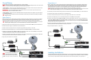
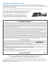

FIGURE 6. Antenna (without reflector) installed parallel to centerline of RV
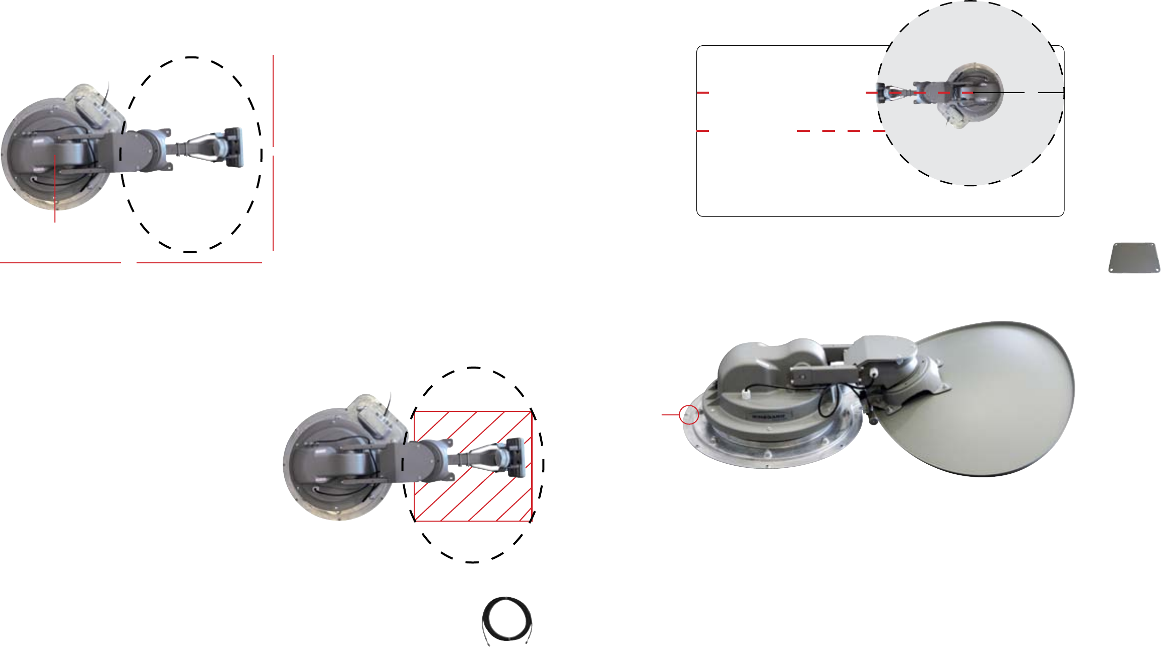
FIGURE 7. Marked “FRONT” of transition plate on fully assembled antenna
“FRONT”
43
CL-SK26
Sold Separately
R
e
f
l
e
c
t
o
r
(
N
o
t
Y
e
t
A
t
t
a
c
h
e
d
)
R
e
f
l
e
c
t
o
r
(
N
o
t
Y
e
t
A
t
t
a
c
h
e
d
)
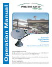
34″
Center of Base
44″
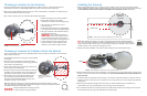
FIGURE 4. Required roof space for antenna
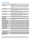
FIGURE 5. Marked area of
antenna where cables should
not be run
Installing the Antenna
1. Place the TRAV’LER antenna on the roof where you plan to install it. On the mount base, the transition plate is
marked “FRONT” and “BACK.” Rotate the TRAV’LER antenna until the front of the mount base faces the front of the
RV. The TRAV’LER antenna must be installed on or parallel to the centerline of the coach. See figure 6.
TIP
When installing the antenna on a rubber roof, Winegard recommends using Model SKA-004
roller plate, which is designed to create a solid landing area for the roller. If not using this plate,
make sure that the roller does not come in contact with any rib supports or bubbles in the roof when in
operation. Failure to do so may result in damage to the roof.
2. Verify that the marked “FRONT” of the transition plate is facing the front of the vehicle (see fig. 7).
3. Mark the location where the nine screw holes will go. It is important that you can see these marks on the roof of the
RV. Then, move the mount base out of the installation area. It is recommended that you do not pre-drill the screw
holes at this time.
4. To prevent water from getting into the mount base, use a solid line of approved sealant to connect the marks in
the shape of the base. This step must be completed, or the unit will fail due to corrosion. Replace the TRAV’LER
antenna base.
5. Before using the supplied mounting screws, check with your vehicle manufacturer for any special screw
requirements. Then, screw the antenna base to the roof using nine mounting screws.
6. Run a solid bead of sealant around the edge where the transition plate meets the roof, making sure to cover each
screw head. Be careful not to get any sealant above the transition plate.
Choosing a Location for the Antenna
1. For best performance and to reduce signal acquisition time, park the vehicle on a level surface that is free of
obstructions such as trees or large buildings. Make sure you have a clear view of the southern sky.
2. Before removing the TRAV’LER antenna from its box, contact your RV dealer or manufacturer. Your RV may be pre-
wired or have a reinforced area for this system.
3. Then, choose a location on the roof that meets the following requirements:
a. Offers enough support for a secure installation
b. Allows dish to raise and rotate without
interference from other roof-mounted equipment
c. Has a minimum roof space of 44” x 34” for
antenna (see fig. 4)
d. Lacks obstructions taller than 10” mounted within
a 33” radius from the center of the TRAV’LER base
e. Has a gap of less than 3/16” between the bottom
of the antenna and the roof
WARNING
Do not install the antenna in a
location where a gap of 3/16” or
more exists between the bottom of the antenna
and the roof, as the antenna may damage the roof
f. Is within 5 degrees of level, or the system may
require more time to locate satellites (for best
operation, must be within 3 degrees of level)
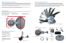
Choosing a Location for Cables to Enter the Vehicle
Once you have chosen a location for the TRAV’LER antenna, choose a location for the cables to enter the vehicle.
Keep in mind the following:
1. The TRAV’LER interface box must plug into a well-ventilated
110 V outlet.
2. The 24” AC power cord must be long enough to extend
from the outlet to the interface box power supply, which will
then connect to the interface box.
3. The 30’ control cable must be long enough to extend from
the mount base to the interface box.
4. The power inserter must be mounted inside the vehicle, but
the splitter can be mounted on the roof of the vehicle (see
Setup Option 1 & Setup Option 2 under “Overall Setup”).
5. Wires should not be run through the striped area (see
fig. 5). Anything in the striped area will interfere with
the operation of the TRAV’LER antenna and may cause
damage to the object or to the antenna.
Make sure cables are long enough to reach their destination points inside the vehicle. For cable
runs longer than 30’, an extension may be purchased. Winegard recommends using Model CL-SK26
25’ extension cable. Do not exceed 55’ of cable!
WARNING
Winegard is NOT liable for damage, expenses,
or injury caused by improper installation.
No obstructions
taller than 10″
in a 33″ radius
Centerline of RV
33″
Front of RV
Mount on or parallel to Centerline of RV
SKA-004
Sold Separately