Dealer Service 23
MAN0306 (Rev. 6/16/2006)
Spool Repair
Whenever repairing spools or positioner, replace valve
spool seals which are included in the spool seal repair
kit.
Disassemble
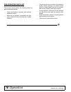
Remove the joystick assembly and/or single lever con-
trol from valve. Remove the plastic dust cap from posi-
tioner (5, 6). Unscrew the positioner assembly from
valve housing. Push spool (7, 8) out of housing.
Secure spool in vise taking care not to scratch or nick
the outer surface. Unscrew the positioner from spool.
Remove brass sleeve (9) and O-ring (10) from posi-
tioner end of valve housing. Remove O-ring (10) and
flange washer (11) from control lever end of valve
housing. The boom spool has a special sleeve with two
O-rings.
Check spools, replace if nicked and scratched.
Carefully inspect spool bore in valve housing. If deep
scratches or scouring is present, entire valve should be
replaced.
Assemble
Clean threads on positioner and spool. Apply a remov-
able-type thread locking compound to male threads
and assemble positioner to spool. Torque to 85±15 in-
lbs.
Apply clean oil to O-ring (10) and install, along with
brass sleeve (9) on spool housing positioner end. Slide
spool into valve housing. Torque positioner end cap (5,
6) to 70±15 in-lbs.
Reassemble the O-ring (10) and flanged washer (11)
on control lever end of spool. Boom spool does not use
a flange washer.
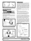
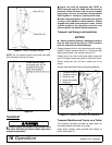
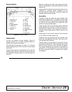
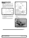
Position spool wipers (A) (Figure 18) on swing, dipper,
and bucket spools in linkage plate. Reinstall control
linkage. Note the screws installed in the boom and dip-
per spools should be tightened until snug, then backed
off approximately ½ turn to allow free movement of the
joystick.
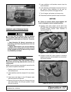
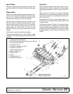
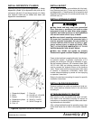
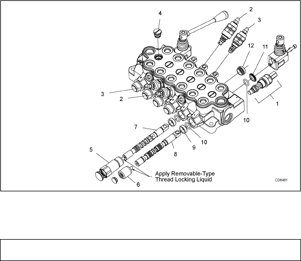
Figure 17. Control Valve Assembly
1. System relief valve 2000 psi
2. Port relief valve with anti cavitation check 2000 psi
3. Port relief valve 2500 psi
4. Load check valve
5. Positioner, 4-position with float
6. Positioner, 3-position
7. Spool, 4-position float (1)
8 Spool, 3-position (5)
9. Sleeve, Lower
10. O-ring
11. Flange washer (5)
12. Sleeve, boom spool (1)


