


2
INSTALLATION
QUICK-START
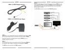
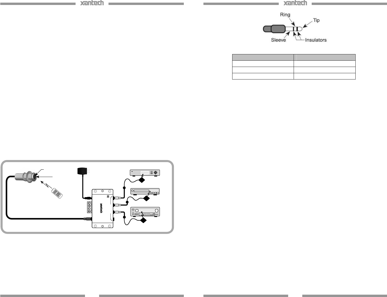
A typical system will use an IR receiver, several emitters, and a power supply
all connected to a connecting block.
1. Connect the IR receiver to the “IR RCVR” port on the connecting
block. The ‘red’ connector is installed to the ‘red’ plug.
Note: In some extended distances, additional 3-conductor may be required and can be
connected to the terminals on the connecting block.
2. Connect the Emitters to the connecting block. The ‘yellow’ connector
is installed to the ‘yellow’ plug.
3. Connect the power supply to the connecting block.
4. Installation complete
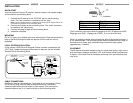
MOUNTING
Drill a 1/2” hole in any surface, such as a cabinet panel. Pass the lead and the
body of the ML85 through the hole and secure from the rear with the nut
(supplied).
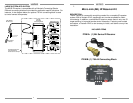
LOCAL SYSTEM APPLICATION
In this system a 283D Blink-IR Designer Emitter is shown connected to the
“OUT” jack. If expansion beyond two emitters is required, use the included
Xantech 789-44 Connecting Block.
CABLE CONNECTIONS
ML85s may also be used where the 7-foot cable is not long enough. Simply
cut off the mini plug, strip the leads and splice them to a 3-conductor
extension cable with a terminal block or other means. Then connect the
extension cable to the 3- or 4-terminal block on the connecting block.
ML Series
IR Receivers
To 120 VAC
(unswitched)
781ERGPS
789-44
Connecting Block
Hand Held
Remote
A/VReceiver
DVD
IRPhotodiode
Talkback LED
Satellite Receiver
283D Emitter
12VDC
+12VDC
GND
STATUS
IRIN
EMITTERS
IR
RCVR
789-44
CONNECTING BLOCK
®
283D Emitter
283D Emitter
3
3.5mm mini plug Signal Name
TIP SIGNAL
RING GROUND
SLEEVE +12VDC
The 3-conductor inter-room cable (24 gauge up to 200’, 22 gauge up to 600’,
20 gauge up to 2000’, 18 gauge up to 5000’), is run to the main room.
While it is possible to make wired connections without the connecting block, it
is not recommended. The connecting block reduces installation time, helps to
eliminate errors, allows easy troubleshooting and permits easy system
upgrades later, if needed.
PLACEMENT
The IR receiver should be located so that it is not directly facing a light source
such as lamps or displays (standard, LCD, and Plasma). When mounted near
a display, it should be flush to the display and away from light reflections that
may occur.