


8
IR Troubleshooting Guide
NOTE: Due to the many variables in a given installation, the
troubleshooting countermeasures you will have to take may vary from job
to job. Each installation is different due to the number of IR receivers in
use, length of wire runs, type of wire, amount of ambient IR noise present,
etc…. Therefore, your countermeasures for a particular job will range
from nothing at all, to any combination of the solutions listed below.
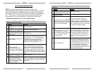
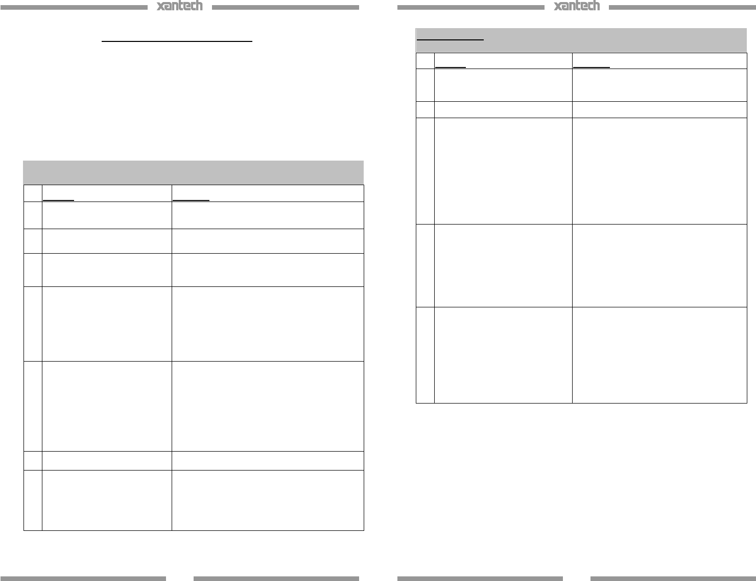
IR Receivers: Model #’s DL, HL, ML, and WL series
Symptom #1: DIM or NO Talk Back LED during IR Reception or
reduced operational range
Cause: Solution
1.
Weak Batteries in Transmitting
Remote.
Replace batteries.
2.
Bad Emitter or no emitter
plugged into connecting block.
Test emitter and verify wiring.
3.
Signal wire between IR
Receiver and the Connecting
Block is open.
Recheck wiring.
4.
Power Supply not putting out
proper voltage.
Verify supply is a 12VDC regulated supply
reading between 11.5 to 13VDC under load.
Should be using Power Supply Model
781ERGPS (12VDC Regulated, 200mA) or
782ERGPS (12VDC Regulated, 1.2A)
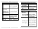
5.
Output from the IR
receiver/connecting block is
connected to a high impedance
IR input jack on a component.
If you are using a passive connecting block,
such as a 789-44, and the system is not
working, try the amplified connecting block,
model 791-44. Put one of the small plastic
case jumpers supplied with the block on the
pins next to the emitter jack. This will provide
the IR-in jack on the component with a hotter
signal.
6.
IR Receiver is inoperable.
Replace Receiver.
7.
(XTRALINK Only) RF
Amplifier is being used on
same COAX Line anywhere
between the Coupler (CPL94)
and Injector (INJ94).
Need to use a Bypass Kit (model BYPASS94
Kit) to route the IR control signals around the
amplifier(s).
9
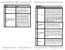
Symptom #2: TB LED on IR Receiver (and/or Emitters) Dimly lit or
flickering
Cause: Solution
1.
Signal and ground wires are
reversed or shorted either at the
connecting block or IR receiver.
Recheck your wiring.
2.
Defective emitter.
Replace Emitter
3.
Relatively high levels of ambient
noise. This can be due to any of
the following: Sunlight, florescent
Lighting or Plasma Displays.
In this case use either a SUN filter
(SUNKIT), or any of our ‘Plasma/CFL
Friendly’ IR Receivers (DL85/9
5, HL85/95,
ML85/95, WL85/95). These can also be
used in direct sunlight and in the presence
of ‘tube style’ fluorescent lighting.
4.
EMI induced noise. This can be
due to light dimmer controls or
other radiating electronic devices
(PC’s or any poorly shielded
electronic device).
Reposition IR Receiver and/or cabling
away from emitting device. You can also
place a 470Ohm resistor in parallel with
the IR Signal and GND connections on
the connecting block. This will also help
alleviate any stray capacitance in the
cable.
5. Plasma Interference
Use an 85 or 95 series Plasma 'Friendly'
IR Receiver. If already using a 85 or 95
unit, please note the Plasma interference
can be reflected off of any item it comes
into contact with within approx. 3ft. From
the front of the display. Keeping this in
mind, make sure that the IR receiver is
free from any obstruction that might reflect
back into the receiving eye.