


12
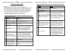
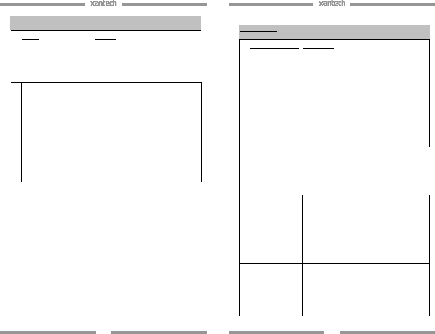
Symptom 6: Emitters function but some (or all) components do not
respond.
Cause: Solution
1. Emitter placement is incorrect.
Reposition the Emitter so that it is directly
over the components sensor window.
Consult the components owners’ manual of
the unit for the exact location of the IR
Sensor Window.
2.
Emitter placement is correct
but the signal is overpowering
the unit or there is bleed-
through from other emitters
close by.
Reposition the Emitter to a position that is
suitable for the unit. Use a 283 o
r 286D Blink
style emitter (they have a lower output than
non-blink emitters 282 and 284M). If the
components do not need to be controlled
directly without an IR Repeater system
(components are located in an equipment
closet), place a Mouse Emitter Shield cover
over the Emitter (PN#MS1). The rounded
(non-stick) side of the emitter is a hi-output
side and can reflect off other devices and
overpower some components IR Sensors. If
using a CB12 connecting block, try a 789-44
connecting block. This has a series resistor
at the output, which will limit current to the
Emitter.
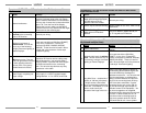
13
Symptom #7: Absolutely No Functionality (How to determine which
component is at fault)
Component to Test Instructions
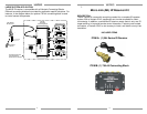
1. Verify Power Supply
With a Multimeter, measure the DC Voltage of the
supply while it is connected to the Connecting Block.
Put the Negative lead of the meter on the terminal
marked GND and the Positive Lead on the terminal
marked 12VDC (or V). You should get a reading
between 11.5VDC and 13.0VDC. If not, remove the
sup
ply from the Connecting block and measure again
this time directly on the 2.5mm Coaxial plug. If it
reads between 11.5VDC and 13VDC, power supply is
most likely good. Reconnect to the Connecting Block
and proceed to step 2. NOTE: In most cases this
will in
dicate the supply is good but in some cases
the supply can still be bad (i.e. reads good when
not plugged in but may not be able to handle the
current load of the system.)
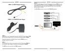
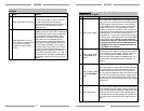
2.
Verify Emitter. (283D
or 286D Blink Style
ONLY)
Remove the power supply from the connecting block
and all Emitters from the output. Place a jumper wire
on the connecting block between IR and +12v.
Reconnect the Power Supply and one emitter. The
Emitter should Light bright and solid. Repeat for all
emitters.
3.
Verify Emitter. (282M
or 284M NON Blink
Style)
Use a diode tester to verify proper Emitter operation.
Remove Emitter from Connecting Block. Place the
Positive Lead of the tester on the TIP of the Mono
Mini Plug and the Negative Lead on the Shield of the
Mono Mini Plug. Meter should read a voltage. When
the leads are reversed (Positive lead on Shield and
Negative lead on TIP) you should not get any voltage
reading at all.
4.
Verify IR Receiver.
Remove the power supply from the connecting block
and all Emitters from the output. Place a jumper wire
on the connecting block between IR Signal and GND.
Reconnect the Power Supply. With a known good
hand-held remote, shoot a constant IR Command at
the receiver and verify the TB LED on the Receiver
lights.