


6
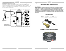
ITEM C: (4) 283D Designer Emitters
ITEM D: (1) 781ERGPS Power Supply
STEP 1:
Plug in the 2.1mm Coaxial power plug of the 781ERGPS Power Supply (ITEM
D) into the jack labeled 12VDC on the 789-44 Connecting Block (ITEM B).
Plug the AC end of the 781ERGPS Power Supply (ITEM D) into a ‘un-
switched’ 120V AC Line outlet.
STEP 2:
Connect the 3.5mm stereo mini plug from the 481D IR Receiver (ITEM A) to
the ‘IR RCVR’ input located on the 789-44 Connecting Block (ITEM B).
The RED connector connects to the RED receptacle.
7
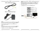
STEP 3:
Plug in the 283D Designer Emitters 3.5mm mono mini plug (ITEM C) into the
jacks labeled EMITTERS on the 789-44 (ITEM B) and affix the opposite end
to the IR Sensor Window of the controlled equipment. Extra double sided
adhesive tape is included.
The YELLOW connector connects to the YELLOW receptacle.