


9
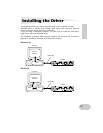
Parts and Functions
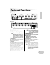
Front panel
Rear panel
A ON/STANDBY switch
Press this switch to turn the power to
the UX256 on or off (standby).
Even when the power is off
(standby), a small current flows
through the unit. If you plan not to
use the UX256 for a long period
of time, be sure to remove the
power adaptor from the AC outlet.
B POWER LED
This indicator lights up when the power
to the UX256 is turned on.
C USB LED
This indicator lights up when the UX256
is connected to the computer and ready
for use. It flashes when the UX256
receives or transmits MIDI signals.
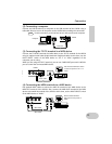
D TO TG terminals 1 and 2
Connect these terminals to the TO HOST
terminals on the MIDI devices. Use an
optional 8-pin system peripheral cable for
Apple Macintosh for connection.
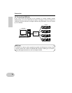
Set the HOST SELECT switch
of the connected MIDI device
to “PC-1” or “Mac” regardless
of the computer you are using.
E MIDI terminals 1-6
Connect MIDI devices to these terminals
using MIDI cables.
MIDI IN: Receives MIDI signals.
MIDI OUT: Transmits MIDI signals.
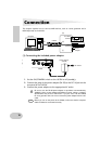
F USB terminal
Connect this terminal to a computer or
a USB hub using a USB cable.
G DC IN jack
Connect the PA-3B power adaptor here.
Before connecting the power
adaptor, make sure that the
power ON/STANDBY switch on
the unit is set to off (standby).
Connect the power adaptor to the
DC IN jack, then plug the adaptor
into the AC outlet.
4321 5
467
NOTE