Page 15
206-4065
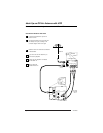
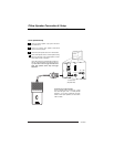
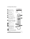
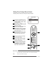
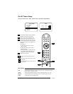
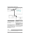
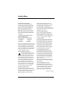
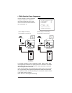
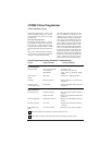
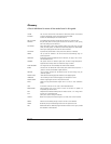
Pillow Speaker Setup
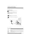
Connect a pillow speaker to the TV
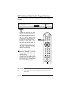
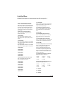
Pillow Speaker Control
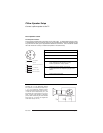
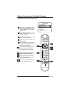
Pillow Speaker Interface
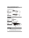
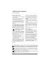
This connector furnishes three control lines and an audio output. A patient-pendant remote control,
or entertainment audio and nurse call system may be connected here. All lines are isolated from the
AC power line and earth ground. (Opto-isolators isolate the control lines, and a transformer isolates
the audio. There are no relays or inductive components in the control lines.)
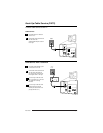
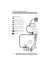
3
TV
ON/OFF
CHAN
DOWN
CHAN
UP
(MALE
PLUG)
VOLUME CONTROL
SPKR.
5
1
4
6
2
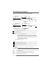
1
2
3
4
5
6
3
1
5
2
4
6
TV ON/OFF
OPEN
CHAN UP/DATA IN
COMMON
AUDIO OUT
CHAN DOWN
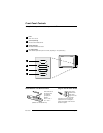
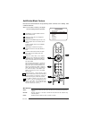
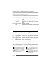
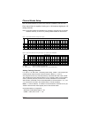
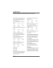
Controlling the TV with Mechanical Switches
Pin 4 (common) is momentarily connected to pin
1, 3, or 6 via push-action switches to control
On/Off and Channel Up/Down. These pins are at
+13 volts DC (when measured from pin 4) with
the switches open. Current draw is 8 mA when a
switch is closed. (This operation is identical to
previous Zenith models using the 5-Wire Interface
except that only +7 volts DC was supplied and
current draw was only 2.5 mA.)
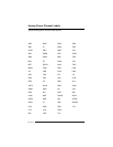
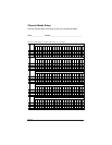
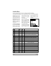
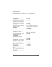
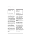
Pin No. Purpose
1 External TV On/Off switch.
2 (Not used.)
3 External Channel Up switch or Data in.
4 Common connection for control, data, and audio
output. Impedance to earth ground is a 10-meg
resistor in parallel with a 1100 pf capacitor.
5 Isolated audio output. Nominal 14-ohm source
impedance with short circuit protection. Intended for
a pillow speaker with a low-impedance pad-type volume
control.
6 External Channel Down switch.