4 MG302-EU-EN V2.0 4/11
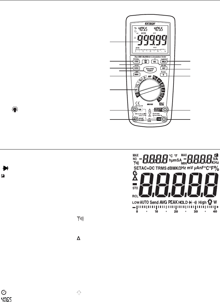
Controls and Jacks
1. 40,000 count LCD display
2. MAX/MIN ( - ) button
3. STORE (<RECALL) button
4. RANGE(SETUP) button
5. INSULATION TEST button
6. MODE button
7. Function switch
8. 10A input jack
9. mA, µA, Insulation (-) jack
10. HOLD (PEAKHOLD>) button
11. REL (+) button
12. EXIT (AC+DC) button
13.
Backlight button
14. Positive and Insulation (+) input jack
15. COM input jack
Note: Tilt stand and battery compartment are on rear of unit.
Symbols and Annunciators
•))) Continuity
Diode test
Battery status
n nano (10
-9
) (capacitance)
µ micro (10
-6
) (amps, cap)
m milli (10
-3
) (volts, amps)
A Amps
k kilo (10
3
) (ohms)
F Farads (capacitance)
M mega (10
6
) (ohms) RF transmitter active
Ohms PEAK Peak Hold
Hz Hertz (frequency) V Volts
% Percent (duty ratio)
Relative
AC Alternating current AUTO Autoranging
DC Direct current HOLD Display hold
ºF Degrees Fahrenheit ºC Degrees Celsius
MAX Maximum MIN Minimum
No. Serial number S second
SET Setup parameter AC +DC Alternating current + Direct current
TRMS True RMS STO Store
RCL Recall AUTO Auto Range
Auto Power off enabled Backlight
Auxiliary Displays
1
8
7
6
5
2
3
4
9
10
11
12
13
14
15


