Model D2424 Reference Manual (Saving and Loading Song Data)
89
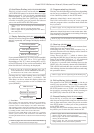
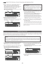
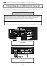
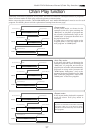
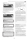
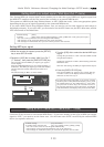
Loading the data using a adat or S/P DIF digital signal
Load the data by S/P DIF digital signals (or adat digital signals) from the [DATA INPUT] jack of the
recorder.
* Restore the initial settings on the recorder.
* Set the same sampling rate on the external digital device and the recorder.
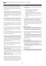
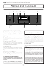
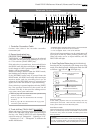
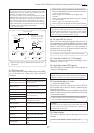
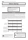
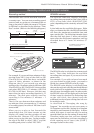
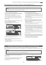
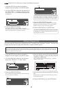
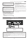
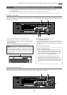
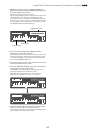
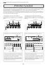
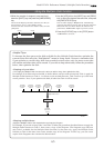
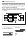
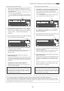
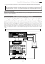
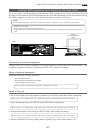
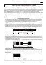
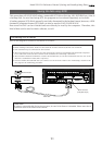
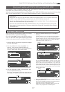
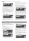
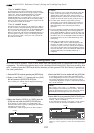
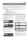
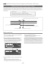
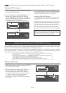
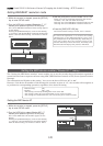
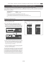
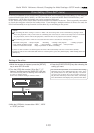
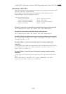
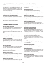
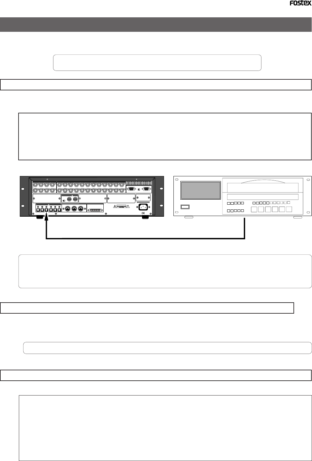
Connecting the external device
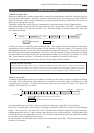
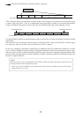
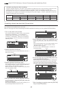
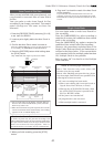
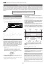
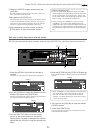
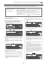
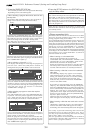
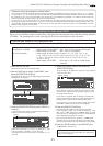
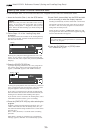
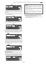
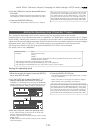
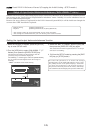
Connect [DATA INPUT] connectors of the recorder to the digital output connectors on the external
digital device.
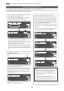
<Notes>
• The recorder has [DATA INPUT] connectors for an S/P DIF digital signal (OPTICAL) and for an adat digital
signal. These connectors have the same shape but carry different information.
Use the [DATA INPUT 1-8] connector. Do not use the [DATA INPUT 9-16] and [17-24] connectors.
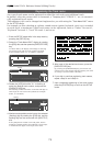
• Do not remove the optical cable or perform any other operation that would disconnect the S/P DIF signal until
the session is complete. Otherwise, the recorder will generate noise, and affect the connected device.
• If the external device has only COAXIAL type (RCA) digital I/O connectors, connect an optional COP-1/96k
(optical/coaxial converter) to use an S/P DIF digital signal.
• Connecting both output and input connectors on the recorder to the input and output connectors on the
external digital device respectively may generate a digital loop.
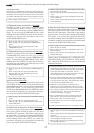
Setting up an external device
1.Setup the external device so that it can output a digital signal.
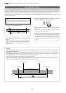
2.Locate the beginning of the pilot signal recorded in the saved data.
* Refer to the instruction manual that came with your external digital device for details.
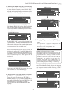
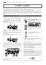
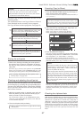
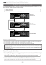
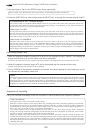
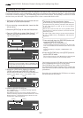
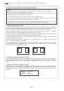
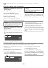
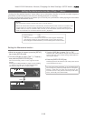
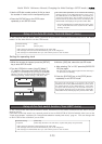
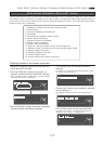
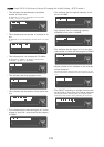
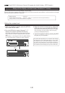
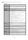
Executing the load operation
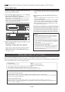
You will use the “Load PGM ?” menu in Setup mode.
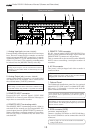
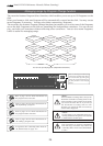
75Ω
WORD
OUTPUTINPUT
OUTPUT
DATA
16 - 9
24 - 17
8 - 1
100Ω
RS422
THRU
AC-IN
INPUT
16 - 9
24 - 17
8 - 1
SCSI
ONOFF
REMOTE
MIDI
INPUT
THRU
OUTPUT
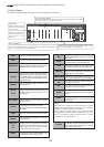
1
2
34
5678
1
234
13141516
5
6
7
8
1718
19
20
9
10
11
12
21
22
2324
NE PAS OUVRIR
CAUTION
AVIS :
RISQUE DE CHOC ELECTRIQUE
WARNING:
TO REDUCE THE RISK OF FIRE OR ELECTRIC
SHOCK, DO NOT EXPOSE THIS EQUIPMENT
TO RAIN OR MOISTURE.
ANALOG INPUT BALANCE [ +4dBu ] / UNBALANCE [ -10dBv ] ANALOG OUTPUT BALANCE [ +4dBu ] / UNBALANCE [ -10dBv ]
ONOFF
DATA
MIDI
WORD
SCSI
REMOTE
ANALOG OUTPUT BALANCE [ +4dBu ] / UNBALANCE [ -10dBV ]
ANALOG INPUT BALANCE [ +4dBu ] / UNBALANCE [ -10dBV ]
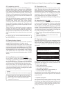
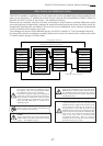
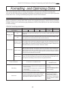
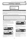
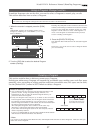
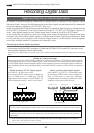
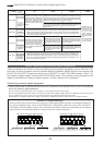
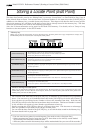
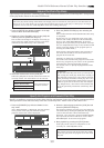
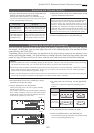
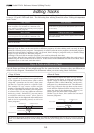
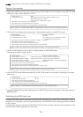
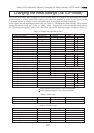
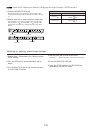
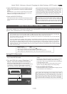
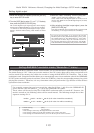
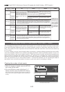
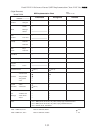
• Input format available : adat, SPDIF, SCSI, IDE2
• Programs available : When using an adat/SPDIF ->P01 - P99 (each program individually)
: When using a SCSI/IDE2 ->P01 - P99 or All program
• Track available : When using an adat or DAT ->Tracks 1-8, 1-16, 1-24, 1-32, 1-40
1-48, 1-56, 9-16, 9-24, 9-32, 9-40, 9-48, 9-56, 17-24, 17-32, 17-40
17-48, 17-56, 25-32, 25-40, 25-48, 25-56, 33-40, 33-48, 33-56,
41-48, or 49-56
: When using a SCSI/IDE2 ->All tracks (1-56) will be automatically
selected.
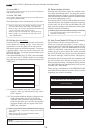
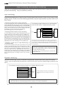
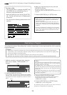
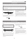
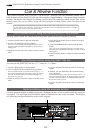
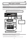
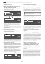
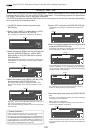
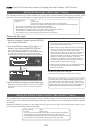
DATA INPUT 1-8
adat or DAT
adat Out (or Digital Out)