21
Connections
Basic Setup
Introduction
To wall outlet
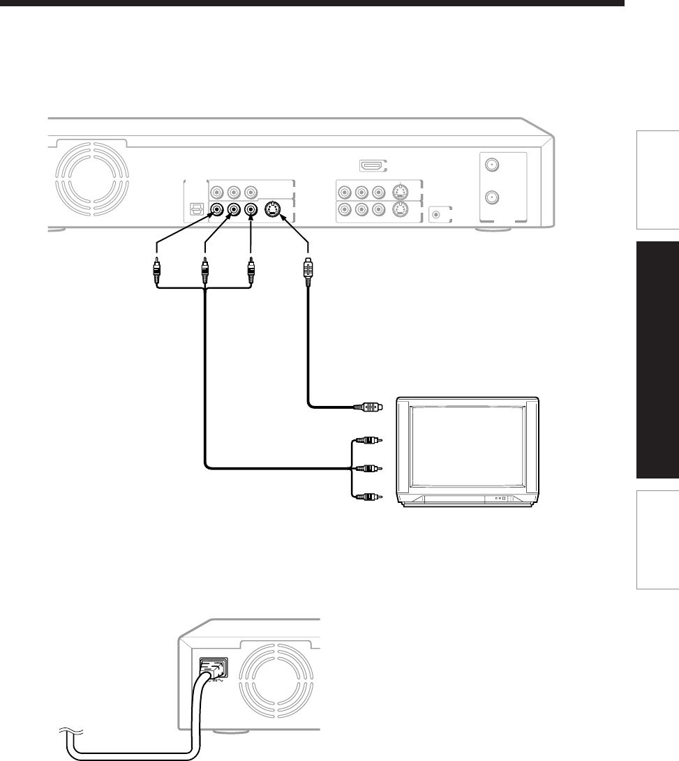
To OUTPUT
(R/L)
Notes
• Refer to the owner’s manual of the connected TV as well.
• When you connect the recorder to your TV, be sure to turn off the power and unplug both units from the wall outlet before any
connections.
• If your television set has one audio input, connect the left and right audio outputs of the recorder to a Y cable adapter (not
supplied) and then connect to your TV.
• Connect the recorder directly to your TV. If you connect the recorder to a VCR, TV/VCR combination, video selector or AV
amplifier, the playback picture may be distorted due to copy protection.
To OUTPUT
(VIDEO)
To OUTPUT
(S-VIDEO)
Video/audio cable (supplied)
If the TV has an S-video input, connect the recorder
with an S-video cable. When using an S-video
cable, do not connect the yellow video cable.
(yellow)
(white)(red)
(red)
(white)
To video inputs (yellow)
To audio input
To S-video input
3
Connect to a TV equiped with audio/video inputs.
Connect as below for watching received channels or recorded contents. Watching via the RF OUT terminal
is not available.
4
Connect the power cord of the recorder to a wall outlet.
Make sure that the powered recorder lights the ON/STANDBY indicator on the front panel.
TV or monitor with
audio/video inputs
S-Video cable (not supplied)
RF IN
(
FROM ANT.
)
RF OUT
(
TO TV
)
VHF / UHF
R L VIDEO
S-VIDEO
RL
IR
VIDEO
S-VIDEO
CHANNEL
CHANGE
DIGITAL AUDIO
OUTPUT
BITSTREAM/PCM
OPTICAL
R L VIDEO
S-VIDEO
YP
B
P
R
INPUT1
COMPONENT OUTPUT
OUTPUT
INPUT3
HDMI OUTPUT
RD-XS52SU/SC_Inst_E_p19-30 04.8.31, 13:0321


