


Routing IP and IPX
A-9
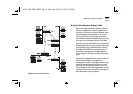
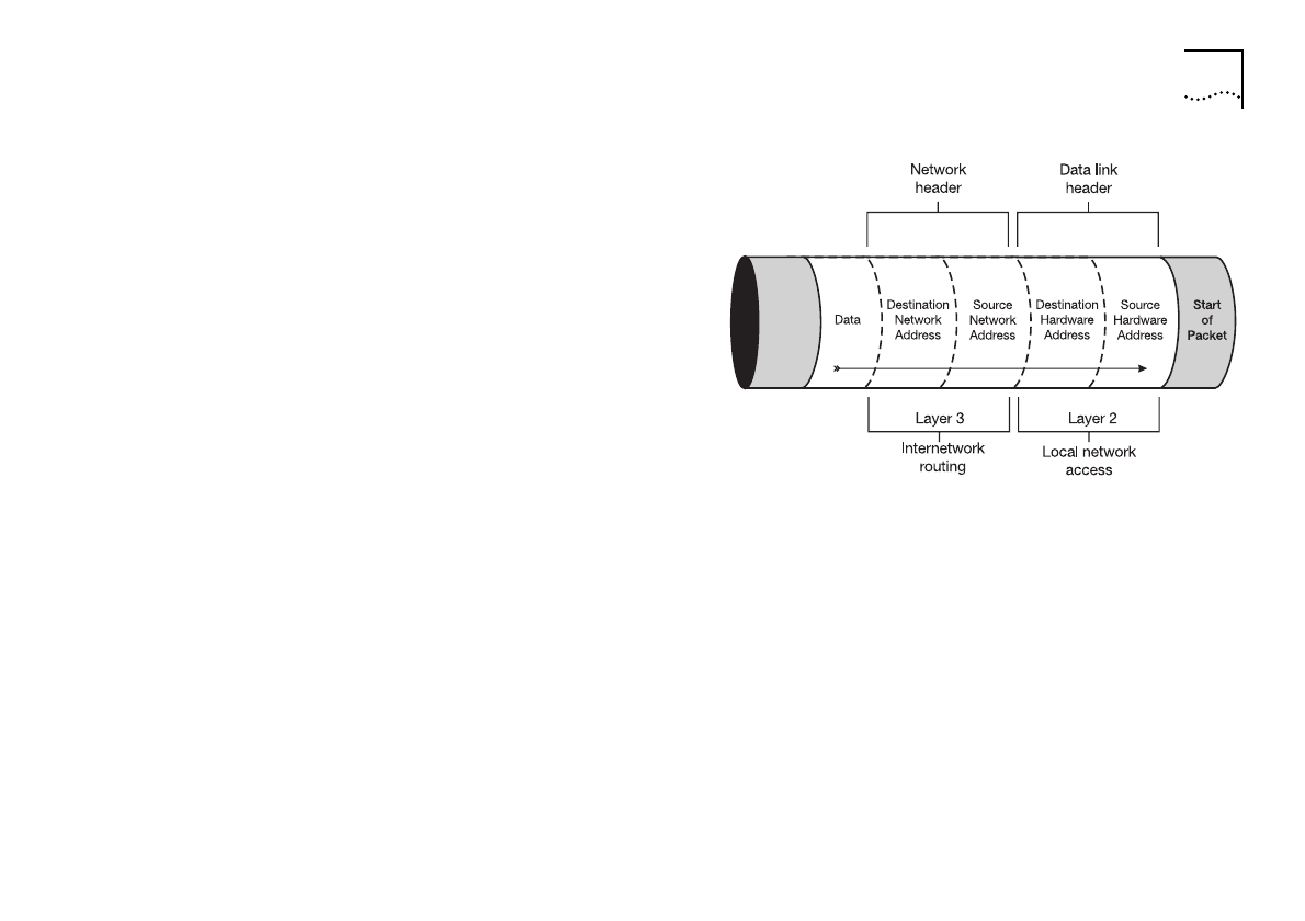
A routing environment allows stations to communicate
indirectly. Following the example in
Figure A-3
, let us
assume that a station on LAN 1 wants to communicate
with a network server on LAN 2. The station on LAN 1,
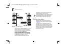
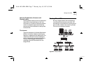
constructs a
Layer 2
datalink header (see
Figure A-5
),
with the source station’s hardware address, and also
the destination hardware address of the local router. To
direct the packet to its final network destination, the
source station must complete the
Layer 3
network
header with the destination network address of LAN 2.
Once the packet is received by the Router A,
attached to LAN 1, it strips off the network header
(refer to
Figure A-5
) and examines the Layer 3
datalink header information. It then reviews its
routing tables in order to establish where to forward
the data packet. It is possible that the LAN 1 router
has multiple outgoing ports that would allow
different transmission routes to the destination
network. In our example using
Figure A-3
, a packet
could go via Router D to get to Router B, or it could
go more directly across a single direct link between
Router A and Router B.
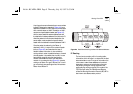
Figure A-5
Data Packet Containing Hardware And Software Addresses
IP Routing
The local router contains, within its routing table,
information which will allow it to determine the best
data transmission route. The type of information the
router uses to make these assessments is protocol
dependent, and some communications protocols
may employ a range of routing algorithms, and
accompanying routing protocols. In the case of the
TCP/IP protocol suite, the OfficeConnect Remote
utilizes the Routing Information Protocol (RIP). RIP is
also known as a
distance vector
protocol.
Rc.bk : RCAPPA.FRM Page 9 Thursday, July 10, 1997 9:53 AM