


1400 Series Granulators Chapter 7: Appendix 41 of 43
7-6 Load Sensing System
The granulator load sensing system stops the feed roll motor and turns on a red light when the
motor current load exceeds the 100% setting on the relay.
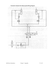
The load sensing system consists of three main components. The current transformer, which
is wired to the granulator, senses the motor current. The load relay receives a signal from the
current transformer. Depending on the setting of the potentiometer (trip current), the load
relay actuates an internal SPDT relay with contacts wired to a terminal block. The relay has
an output signal for a load meter. The load meter receives a signal from the load relay and
measures the percentage of load dependent on the setting of the trip current potentiometer.
When the monitored current exceeds the trip point setting, the output SPDT relay contacts
will operate. When the monitored current drops below the differential value, the output relay
will discontinue. The differential is adjustable from 5 to 25% below the trip point setting.
The factory default setting for the differential is approximately 15%.
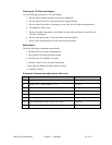
Setting the Load Sensing System
Use the following procedure to set the load sensing system:
1. Determine what the full load amperage of the granulator motor is by reading the
motor nameplate.
2. Determine how much load the granulator should be working at. (For example, if
90%, multiply the full load current of the motor by .09.)
3. With an ammeter, measure the amperage of the granulator motor while loading the
motor. When the motor current reaches the figure determined above, adjust the trip
current potentiometer to read 100% on the meter.