


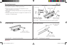
Encoder Installation Procedure SENC 150
Thesestepsapplytoallencodermountingconditions,ifasparis
beingused,goto“SparInstallationProcedure”onpage11.
• ACU-RITE
®
bracket kit instructions supercede this section.
• Adjustdrilldepthsandfastenerlengthsasrequired.
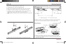
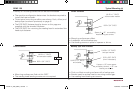
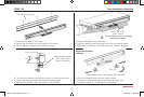
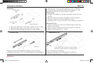
• Wheninstructedonpage10:Adjustthelevelingsetscrewsas
follows:
1.Insert,butdonottighten8-32(M4)readingheadscrews.
2.Placea.001”-.003”shimbetweenthelevelingsetscrews
and mounting surface.
3.Adjusteachsetscrewuntilaslightdragisfeltontheshim.
4.Evenlytightenthe8-32(M4)readingheadmountingscrews.
• ContactyourAuthorizedDistributorshouldyourequire
additional assistance.
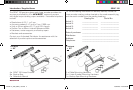
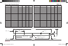
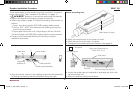
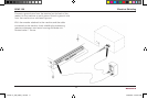
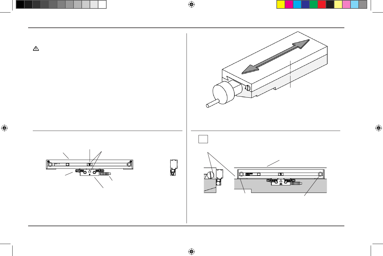
• Alignthecentermarksonthereadingheadandscaleassembly
by sliding the reading head and brackets along the case.
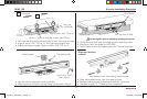
• Locatethescalecasesoundersideofendcapsareushwith
theaxispartingline.
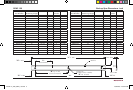
• Markoneendmountingholelocation.
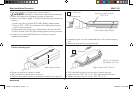
• Movethemachineaxistoitscenteroftravel.
• Marktheaxisforquickreturntocenter.
• Conguretheencodercableexitdirection(seepage3).
Scale case
Reading head assembly
Alignment
brackets (2)
C
L
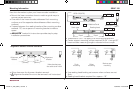
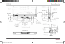
Aligntopofscalecaseto
within.015”of-A-
-A-=Axistravel
Cable assembly
End cap
Scale case
Axispartingline
End mounting hole (typical)
Center marks
Center mounting axis
Markcenteroftravel
C
L
10
ACU-RITE
®
516291-21_Ve00_SENC_150.indd 12 10/22/2009 10:00:43 AM