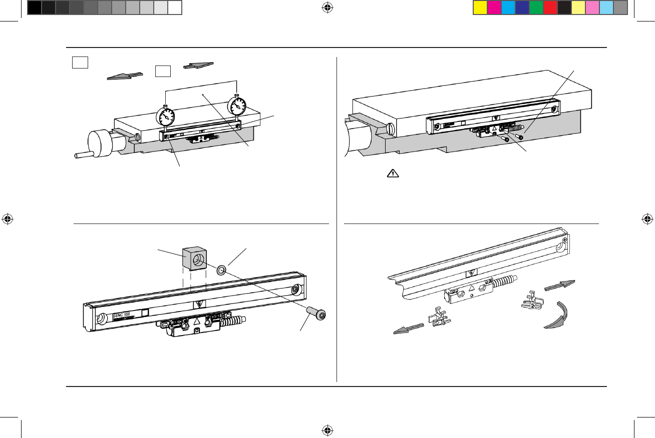
SENC 150 Encoder Installation Procedure
• Drill/taptherstendmountinghole/attachthelinearencoder.
• Aligntowithin.010”TIR.to-A-,drill/tapsecondendhole.
• Attachthelinearencoder/aligntowithin.010”TIR.to-A-.
• Centertheaxisandmarkthereadingheadmountingholes.
• Moveaxis,drill/tapholesfor8-32(M4).
• Attachheadtoaxis/Setlevelingscrews/Securefasteners.
• Usethecentersupport(s)whenprovided.
• Placesupportsatequalintervalsalongtheencoder’slength.
Center support
1/4-20x1”BHCS&Scaleatwasher(M6x25mm)
Aligntowithin.010”TIRto-A-
Drill / tap
for 1/4-20 (M6).
8-32x3/4”SHCS
(M4x20mm)
Drill / tap for 8-32 (M4)
1/4-20x3/4”SHCS
(M4x20mm)
-A-=Axistravel
-A-
Flatwasher(M6)
Do not tighten prior to adjusting leveling set screws
• Slidethebracketsawayfromthereadinghead.
• Removethealignmentbracketsandsaveforfutureuse.
• Proceedtopage13,“CheckingYourInstallation”.
Alignment bracket
removal
Slidebracketsawayfromreadingheadandcable.
Twist45°
11
ACU-RITE
®
516291-21_Ve00_SENC_150.indd 13 10/22/2009 10:00:44 AM


