Appendix A - Specifications 152-402-145-02, Issue 2
32 June 16, 2000 H2TU-R-402
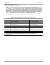
LOOP ATTENUATION
Each loop has no more than 35 dB of loss at 196 kHz, with driving and terminating impedances of 135Ω (see
Table 13 below).
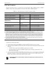
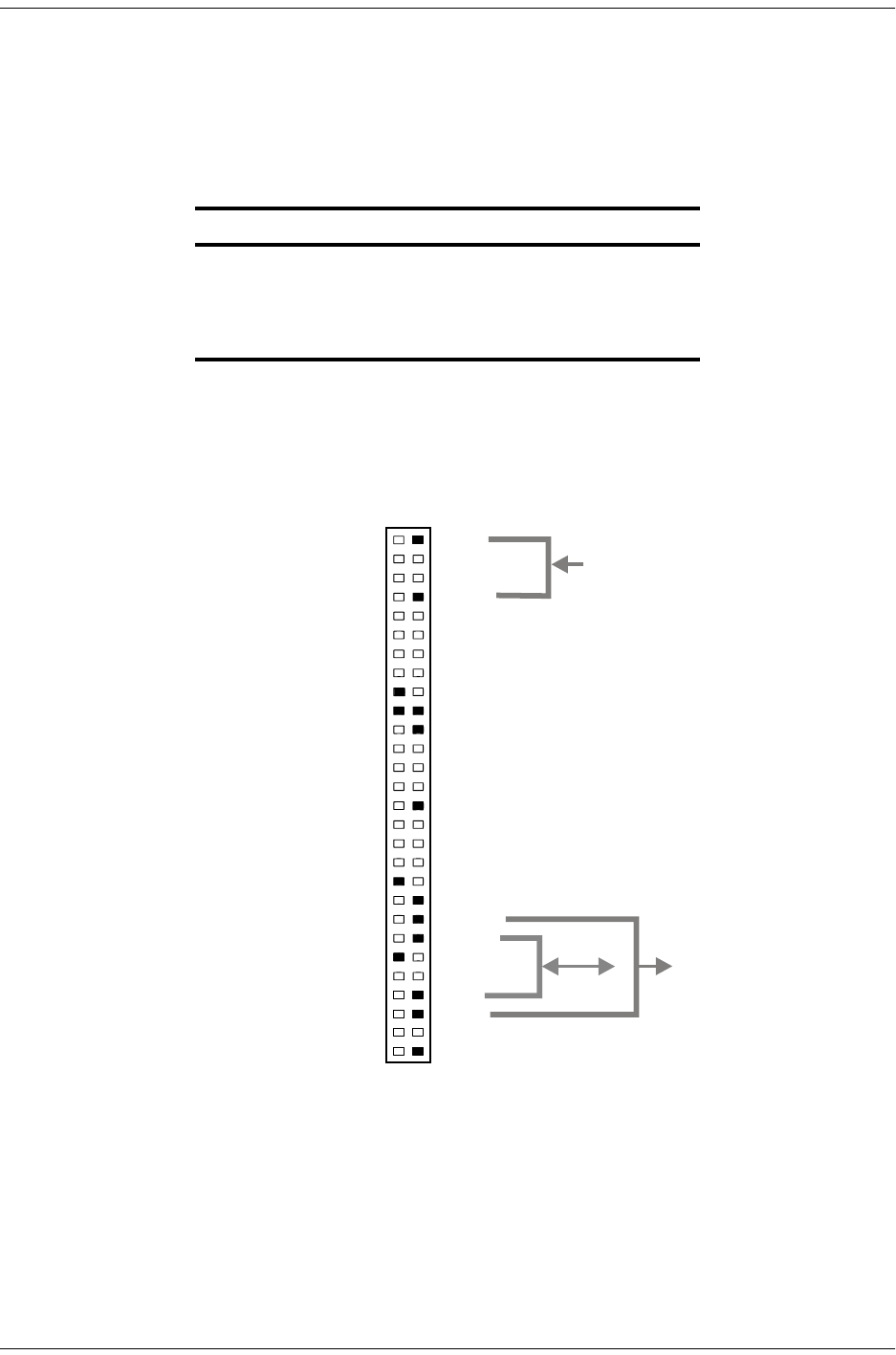
H2TU-R-402 LIST 4E CARD CONNECTOR
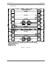
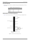
Figure 23 shows the card-edge connectors on the H2TU-R-402 List 4E. Active pins are highlighted in black.
Figure 23. H2TU-R-402 List 4E Card-Edge Connector
Table 13. HDSL2 Cable Attenuation Chart
Cable Gauge Loss at 196 kHz (dB/kft) Ω per kft
26/0.4 mm 3.88 83
24/0.51 mm 2.84 52
22/0.61 mm 2.18 32
19/0.91 mm 1.54 16
27
25
23
21
19
17
15
13
11
9
7
3
5
1
Tip
Ring
Factoryuseonly
Factoryuseonly
Factoryuseonly
Ring1
CircuitGround
Ring
DS1IN
Tip
Tip1
ChassisGround*
ChassisGround*
28
26
24
22
20
18
16
14
12
10
8
4
6
2
55
53
51
49
47
45
43
41
39
37
35
32 31
56
54
52
50
48
46
44
42
40
38
36
34
30
33
29
Active pins are highlighted in black.
* Chassis Ground may be tied to Earth Ground according
to local practice.
HDSL2
Span
DS1OUT
−48V
Automaticprotectionswitchpower
Automaticprotectionswitchcontrol


