


8
ALARM1 IN ALARM4 IN
ALARM2 IN ALARM3 IN
ALARM OUT
RECORD IN GROUND
DISK FULL
ALARM RESET
12345
6789
5V
0V(Active)
5V
0V(Active)
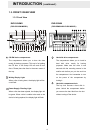
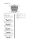
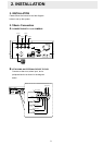
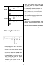
1.4 ALARM In / Out
The above figure is the rear view.
1. GND: Ground Contact.
2. ALARM OUT (OUTPUT): This is an
alarm output trigger. Connect this to
external devices such as buzzers or
lights.
5V
0V(Active)
3. DISK FULL (OUTPUT): This is a disk full
output trigger. Connect this to external
devices such as buzzers or lights.
5V
0V(Active)
4. ALARM RESET (INPUT): This pin
connects to an alarm-clear device for
clearing an alarm.
5V
0V(Active)
5. RECORD IN (INPUT): This pin connects
to a record trigger device for starting a
record.
6. ALARM4 IN (INPUT): This is an alarm
input (for CH 4), which can be
programmed in the menu system to
Normally Open or Normally Closed.
7. ALARM3 IN (INPUT): same as the above,
for CH 3
8. ALARM2 IN (INPUT): same as the above,
for CH 2
9. ALARM1 IN (INPUT): same as the above,
for CH 1