


Chapter 1. Introduction
5
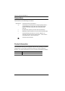
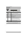
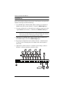
Rear View
Note: The VS1818T’s rear panel is shown on this page. It is similar to the rear
panel of VS1814T except for the number of HDBaseT Out ports – the
VS1814T has 4 HDBaseT Out ports.
No. Component Function
1
Power Socket This is a standard 3-pin AC power socket. The
power cord from an AC source plugs in here.
2
Power Switch This is a standard rocker switch that powers the unit
on and off.
3
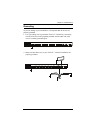
Grounding Terminal The grounding wire attaches here. See Grounding,
page 9, for further details.
4
EDID Mode Switch Press this button to cycle through the EDID settings
stored in the unit (see EDID Mode Selection,
page 12).
5
HDBaseT Out ports
(1~4 / 1~8)
The Cat 5e cables that connects the HDMI Receiver
Units plug in here.
6
HDMI Input port The cable from your HDMI source device plugs in
here.
7
HDMI Output port The cable from your HDMI display device plugs in
here.
8
Firmware
Upgrade button
This button is for enabling the Firmware Upgrade
Mode.
Note: Contact your product provider for details on
upgrading the firmware of your device.
7
RS-232 Serial Port This is the serial remote port for output source
selection and high-end system control, including
firmware upgrade.
1 2
5
963
4
7
8