


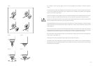

If it is desired to remove the roller glides, use the Torx
®
key supplied with the speaker to remove the retaining
screws.
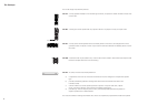
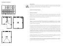
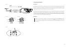
An optional, spike foot kit is also available (Part No FP22359). The kit contains 4 heavy-duty feet that have 40mm
(1.6 in) of vertical adjustment, allowing tilt up to 8
o
if desired. This tilt is in addition to that offered by the adjustable
head unit of the CT8 LR and CT8 CC.
The feet are reversible, having a spike for carpets on one end and a rubber pad for vulnerable surfaces on the other.
Fitting is most easily accomplished during unpacking, when the underside of the speaker is exposed. (figure 7)
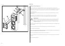
Note that if the optional feet are fitted, or if the speaker is tilted, appropriate allowance over and above that allowed
for in the template must be made when cutting an aperture in the wall.
The threaded bosses that hold the feet have a large conical shape on one side of the flange. For maximum height,
fit the bosses with the conical shape towards the floor. (figure 8) For minimum height, have them pointing into the
speaker. (figure 9)
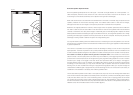
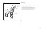
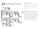
Screw in the feet close to where you think the final adjustment will be, with the spikes or the rubber ends outermost
as appropriate to the floor surface. If you do not intend to tilt the speakers, orient the bosses with the cones inwards
and leave just enough thread exposed to fit the locking rings. Fit, but do not tighten the locking rings.
Stand the speaker upright and adjust the feet using the metal bar provided to give the amount of tilt required and
to take up any rocking. (figure 10)
Finally, tighten the locking ring against the boss, again using the metal bar. (figure 11)
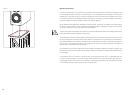
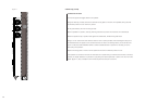
The tweeter drive units are fitted with a protective clear plastic cover on delivery. This is to avoid the danger of
damaging the dome when installing the speakers. Once installed, the protection cover should be removed by simply
pulling it away from the speaker.
11
Figure 1
Figure font: Helv 45, 7pt
Figure spacing: 7 x 7 mm
Figure 2
Figure 3
Figure 4
Figure 5
~40
o
~120
o
~60
o
Figure 7
Figure 6
Figure 8
Figure font: Helv 45, 7pt
Figure spacing: 7 x 7 mm
Figure 9
Figure 10 Figure 11
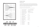
SUB +
SUB
-
SUB +
SUB
-
Figure 15
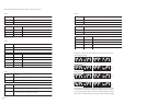
Figure 16a Figure 16b
Figure 17
Figure 14